So remember all those PCBs I ordered?
Let’s break down what worked and what didn’t.
What Worked
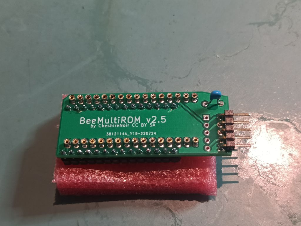
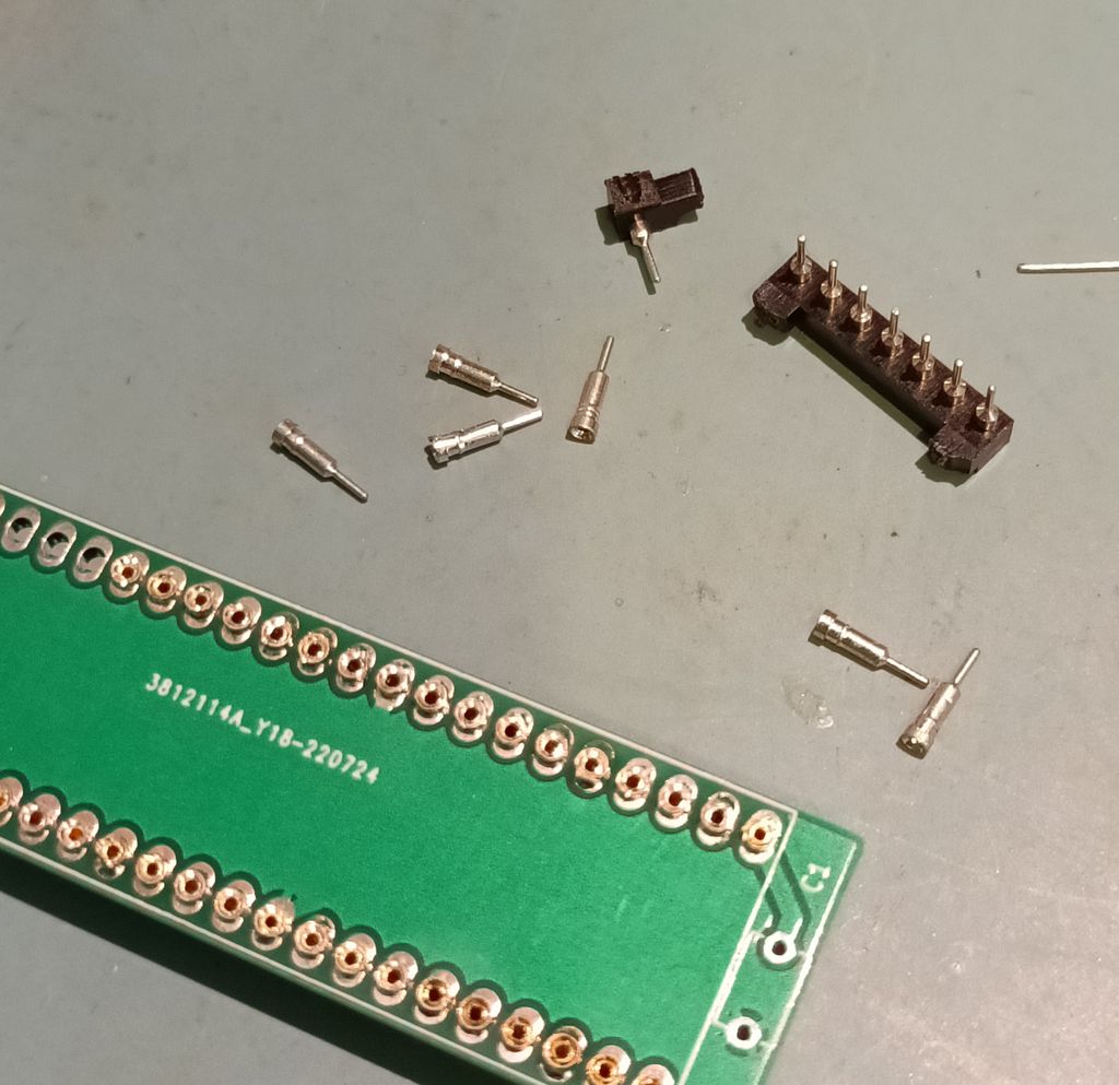
So first up, both my ROM adapters worked without a problem.
So we now have a Low Profile Amiga ROM switcher and a Low Profile Microbee ROM switcher. Both built around using turned pins to keep the profile low.
Excellent!
What Didn’t Work
The Amiga Front Panel had all sorts of odd wiring issues. I redid the circuit, compressing it slightly so it should now qualify for “cheap” construction prices at most board houses. I need to buy some components to check for fit before I order.
I think it was mostly transcription issues going between multiple revisions of the same basic circuit. I also missed a few resistors. Turns out those PS/2 to USB adapters do have some passives in them. To wit a pair of 4.7k resistors between GND and the two data lines. Redone now. I need to check some components for fit, and I’ll be ready to order again.
What “Sort Of” Worked
First the one that “Would have worked if I’d used the right footprint for a component, used the correct sockets and if I’d annotated the schematic with the right resistors…
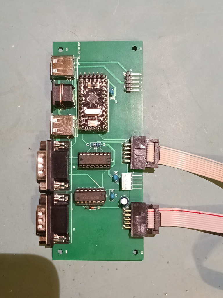
The ArduJoyAdapter looks like it needs a mild respin to work perfectly 🙂
With a bit of bodging, (I managed to somehow find the wrong footprint size for the Opto Isolators. D’oh!) by stretching out the legs of the sockets and carefully bending (And promptly putting them 180 degrees out) and pulling two pins out of each socket (Because I’d been supplied with the wrong sockets, and I couldn’t be bothered driving 20 minutes each way to swap them, so I just shortened them) I was able to mount the OptoIsolators…
It didn’t work.
After much checking and some eventual realisation of various compounded errors, I managed to get the opto isolators in the right way… and it still didn’t work.
Confused, I pulled out my Oscilloscope and set it up. I could see a suitable signal going into the opto isolators, but not coming out. Then it clicked. I was at 1 volt per division on my ‘scope and was barely measuring 2 volts of peak into the opto isolators.
What?
I had breadboarded the whole thing so I checked the one thing that could be impacting the outputs, the resistors I had inline to protect the inputs. On the PCB I had 10KΩ and on the breadboard was 1KΩ. Yep, that’d do it, being out by a factor of 10.
I desoldered the resistors and dropped in suitable replacements and it started working, which was awesome. The next step for that project is I need to program in more functionality. I want to add an autofire option, as well as one or two more modes. There’s an LED there which supports 3 different colours, so that’s not too much of an ask.
What also “Sort Of” Worked
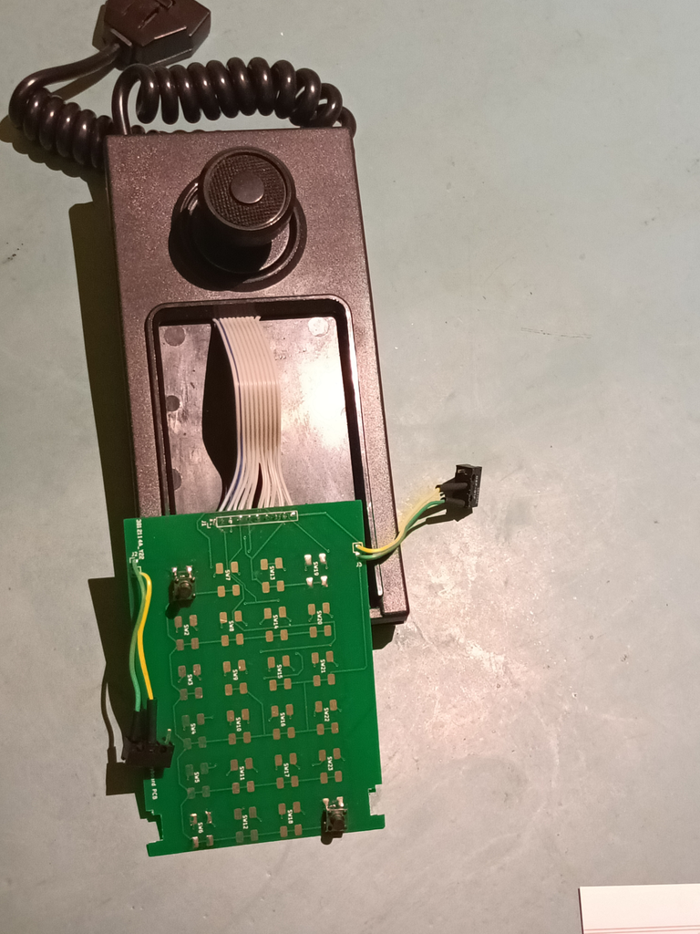
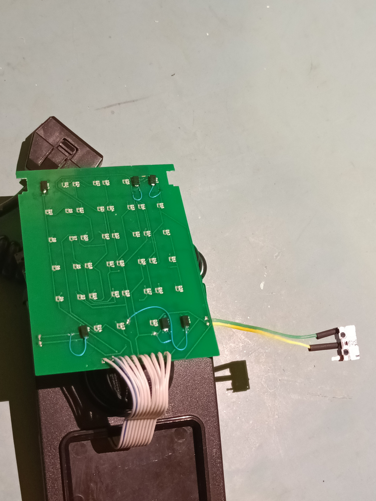
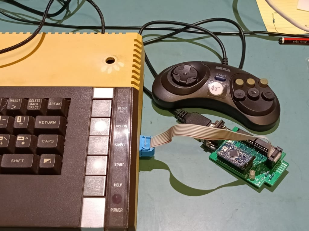
C’mon, I know you have all been wondering how that abomination of a joystick went. The one with 4 different boards?
Well, it worked, at least well enough to prove the concept.
What went wrong? Well…
- Traces that go nowhere. Pin 10 simply vanished off to a dead end between the bottom board and the top board.
- Footprints for components that are 90 degrees out, leading to buttons that are “always on”.
- Pin connections that are backwards on their markings but are correct otherwise. (If you solder the connection backwards to the markings, it works)
- Connections that are too far away from the edge. It causes clashes between solder and the rest of the design.
- Places where the PCB doesn’t allow for penetrations of things like mounting screws and alignment pins
- Buttons that are in the wrong place.
- Buttons that are misaligned.
- A major section that is 90 degrees off. This means that up on the joystick is actually left.
- I couldn’t get the right diodes on the day so I had to wire in ones that were several times larger than what I had designed for.
Despite all that, it actually worked when I’d laid in enough bodges. I was even able to play several different games, and proved all the “leaps of faith” I’d made in the design were all correct. Of course now I have to do a brand new version of the boards. Should be fun!