EDIT: Important Note! PLEASE READ FIRST!
I made a mistake in my assembly pictures. I have assembled this board upside down! It works if you solder everything to the correct side. Don’t be an idiot like me! Solder so the credits face the underside of the PCB not the top.
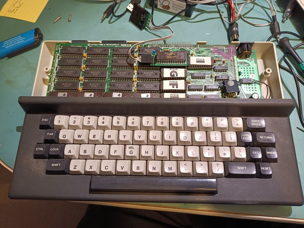
So I have finally got a design for a “MultiROM” ROM changer suitable for use with the PC 85, capable of fitting in a standard case in the ROM H position at IC 22.
https://github.com/cheshirenoir/BeeMultiRom
Assembling these is a little non standard so here’s a guide.
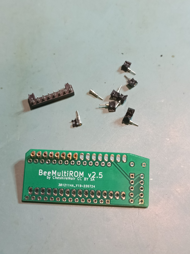
You will need:
- The PCB.
- 32 turned pins. You can either buy these “as is“, or buy turned pin sockets or turned pin strips.
- a 5 pin 4k to 10k resistor pack.
- a 100nF capacitor.
- some header strip. you need two rows of 14. There are a lot of options here. I used machined pin headers, but these will damage your socket. My socket was already damaged. For a less destructive option, consider these.
- Some right angle pin connectors. You need 5 pins.
- A hex switch. More on this later.
- A 27C2001 EPROM with some way to program it.
- A spare wide socket with at least 24 pins. Turned pin makes this easier.
If your pins are in a socket or strip, use a sharp set of cutters and cut them out of their housing. These should drop right into the PCB in the wide holes. Fill all the wide holes.
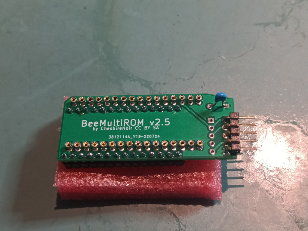
Once you have filled all the wide holes, insert the spare socket into the top of the turned pins. This will aid in soldering.

Flip the board over and solder in all the pins. Remove the socket once complete. If your socket isn’t as long as your pins, you’ll need to add more pins and move the socket.
Once all the pins are soldered in, cut the thin part of the legs off them. Yes, it feels criminal, but we’re using these as sockets, not as pins.
Next we solder in the header strip in the next row of holes, poking down. If you’re using the same strip as me, the default length will be fine. If you’re using something else, be careful with your lengths. If you make them too long, you won’t have enough room to close the lid. Too short and you might hit the socket.
The rest of the components can be added in now. Don’t forget the resistor pack has a polarity. Make sure the dot matches the square pin.
Add your 27C2001 ROM in after programming in images. You have 16 x 16k ROM images in there. Or 32 x 8k ROM images. Or a mix, as long as you keep everything aligned to 16k boundaries. (If you have 8k ROMs, they can be accessed by either PAK4 or PAK12 commands. If you have 16k ROMs, they can be accessed by PAK4)
Finally the bit I have to leave a bit open. This is the hex encoder. There are SO many options here. I’ve tried this and this. Neither is perfect. The first feels flimsy. The second only supports 10 positions, and is too big to actually fit in the case. Either way, you connect the “common” pin of your encoder to pin 1 and 2-5 to the remaining pins. You could probably even rig up a 4 way DIP switch by wiring all the pins on one side together then to pin 1 on the connector. Then connect the other side to pins 2-5.