A Whole Lotta Nothing

I’m not dead. Honest!

It has, however, been a long time between posts. Unfortunately I haven’t been working on project work as much as I would have liked, and I spent a long time waiting for parts to arrive for projects.

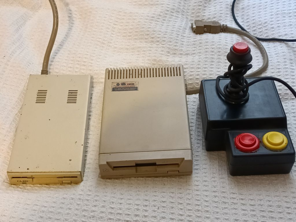
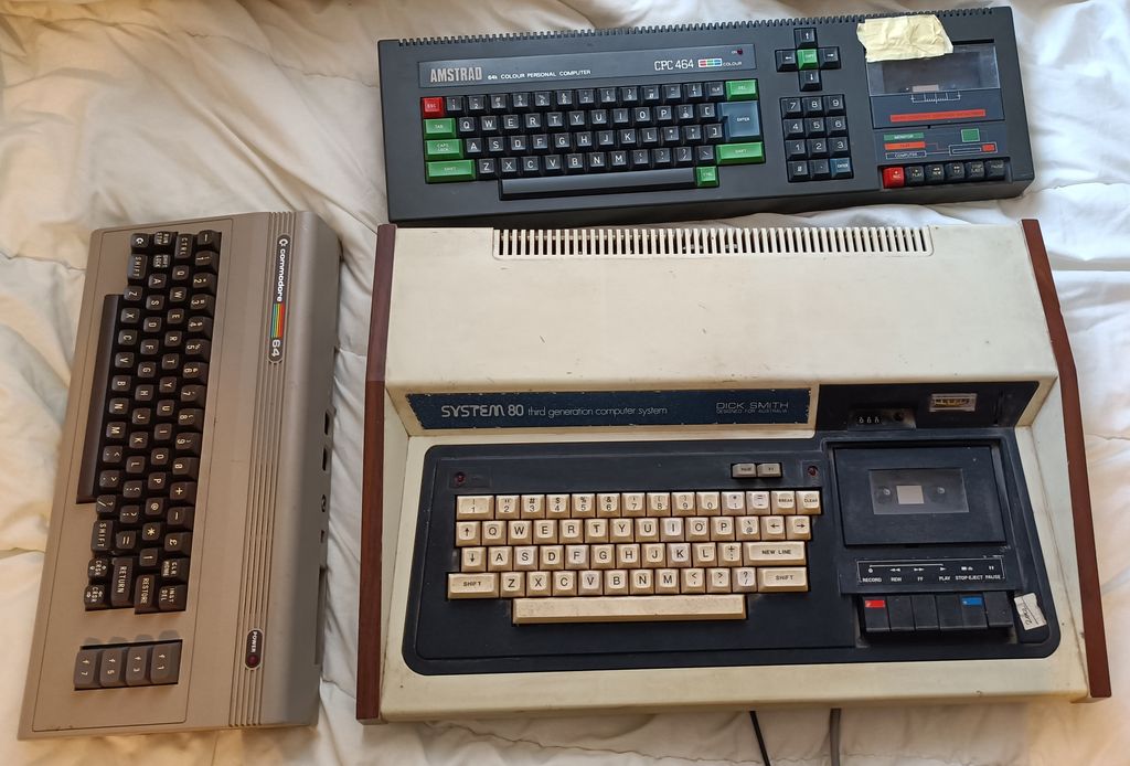
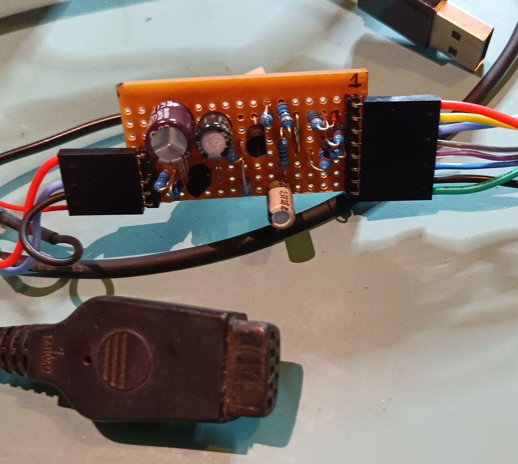
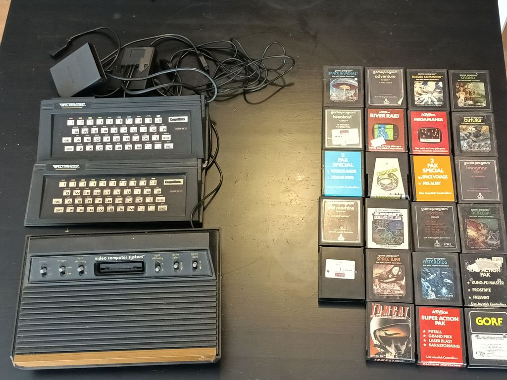
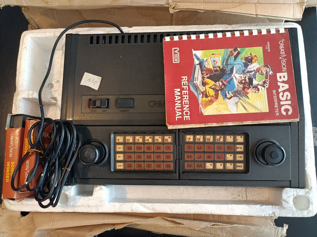
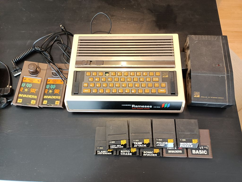
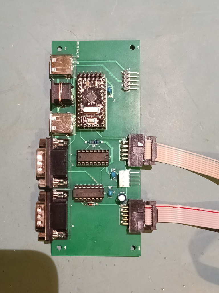
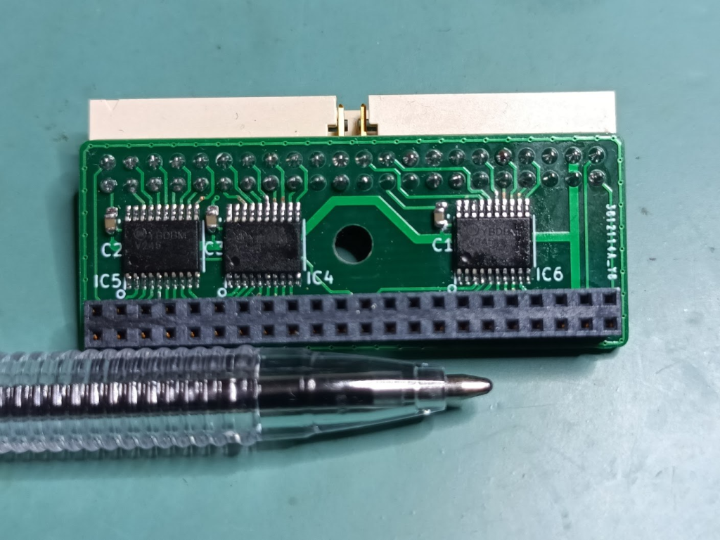
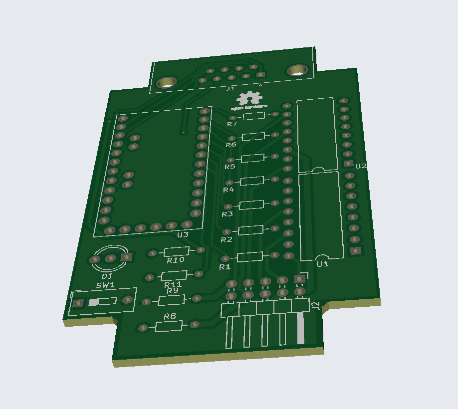
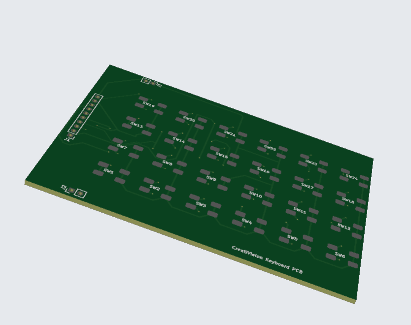
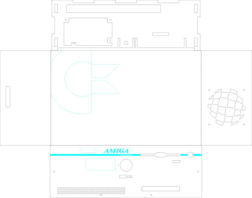
CreatiVision Controllers

(AKA the Dick Smith Wizzard)

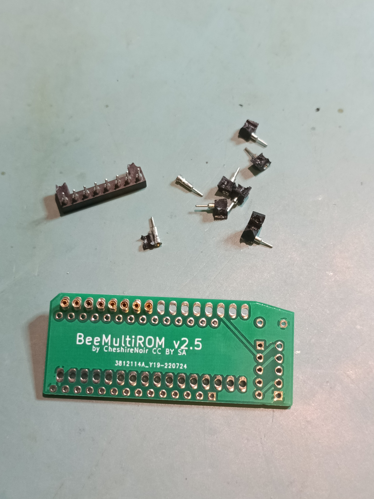
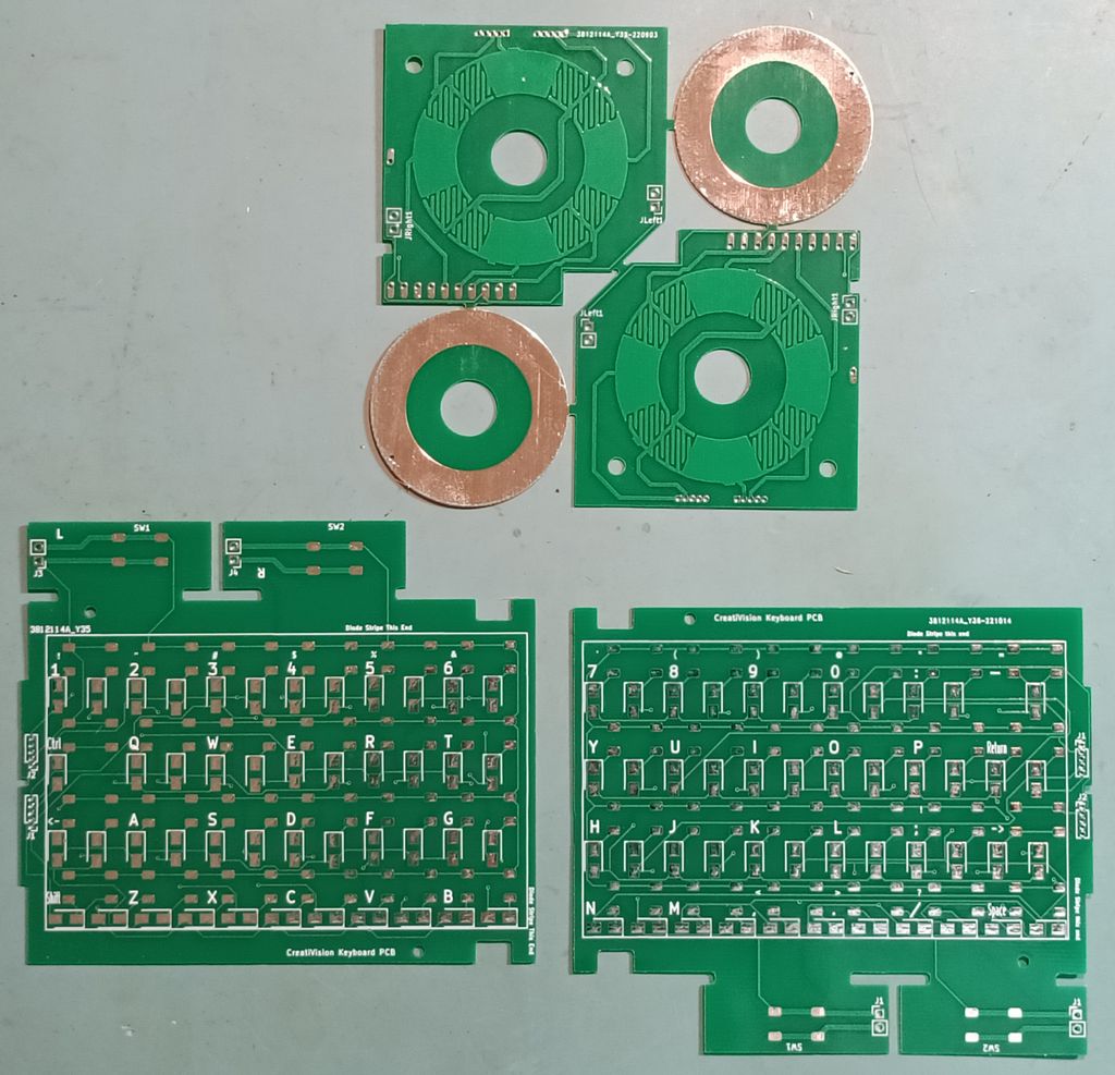
The new PCBs arrived. It took me a few days to get to the shops to buy the appropriate SMD diodes I needed.

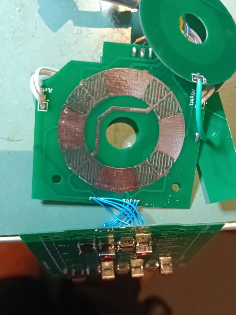
I then spent several minutes tacking in SMD components, followed by the slow realisation that my “clever” idea to use finer spaced soldering holes so I could use ribbon cables wasn’t as “clever” as I’d hoped. Eventually I managed to get everything wired up, tested and… It didn’t work.

Do not use this version. it’s bad.

This was not what I was expecting. This was a revision of a working design. I stopped and put it aside for a week or so before approaching it again. Looking over the PCB I could see issues with connectors being in the wrong place. It looked like I had accidently switched the two connectors. Easy peasy.

Patched again and… It still didn’t work.

Bodge wires of the finest order. Pity they aren’t going to the right places.

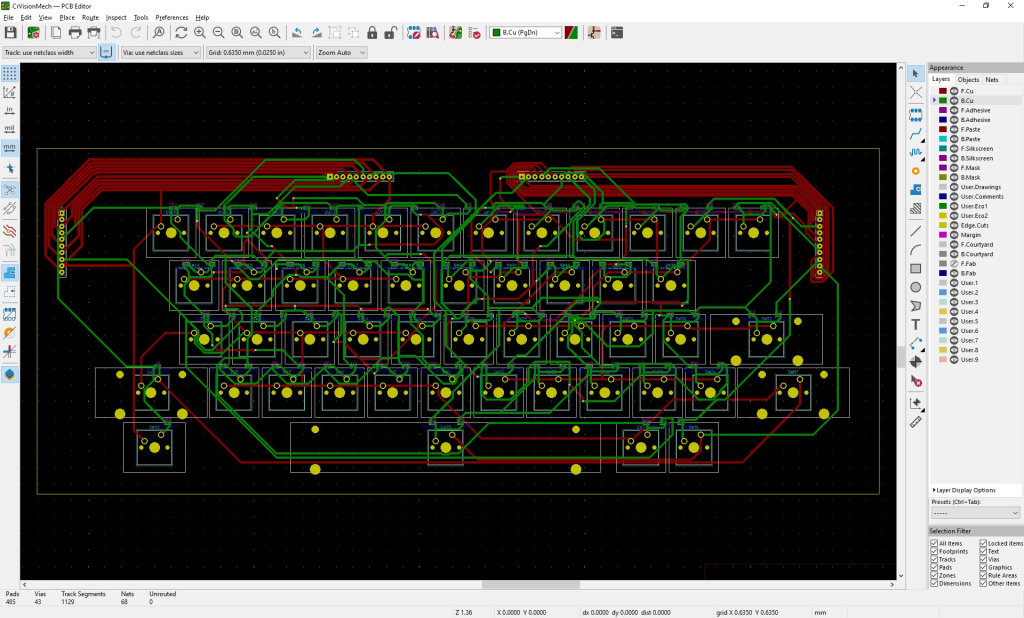
I went back to the PCB printout and started sanity checking… every. single. connection.

After an hour or so of checking I finally twigged. The two connectors were in the right place, just rotated 180°, which really didn’t help 🙂

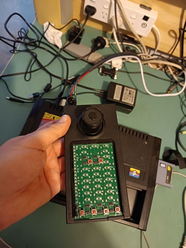
I patched it again, and this time it actually all worked! I’ve moved the fixes back to the main board and I just need to submit it for PCB fabrication.
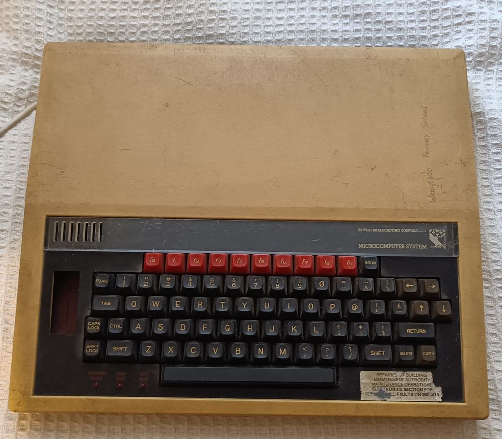
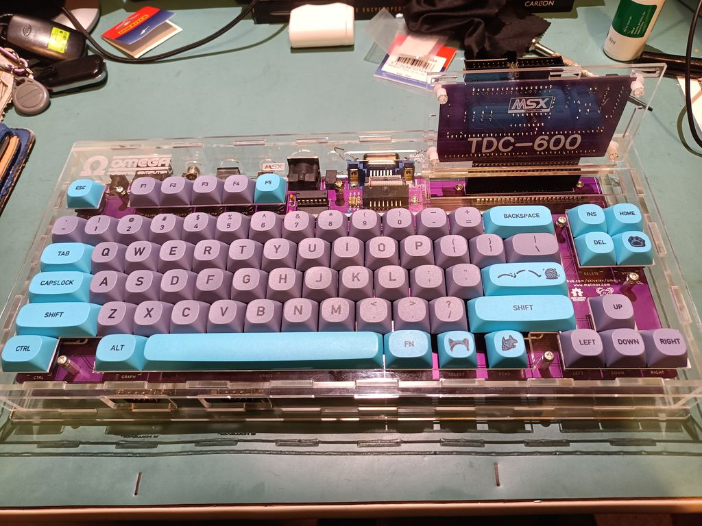
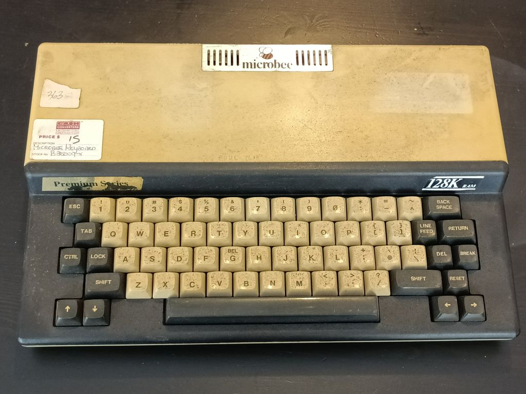
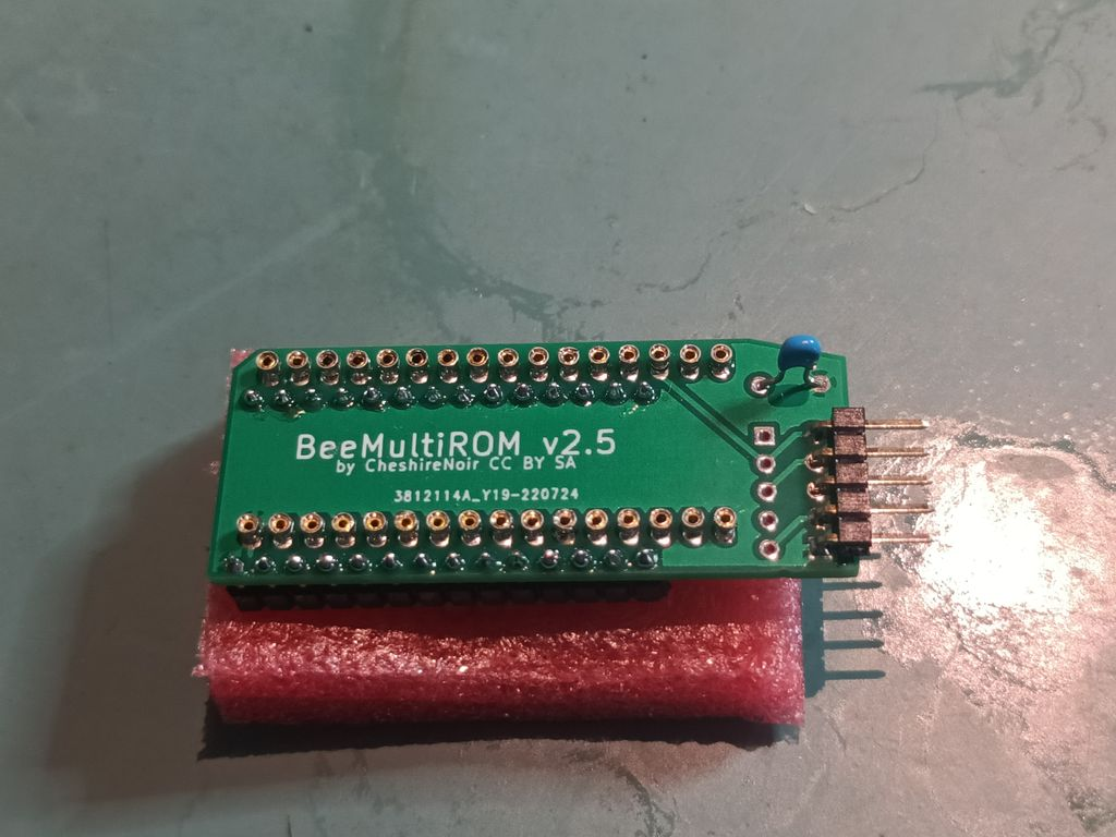
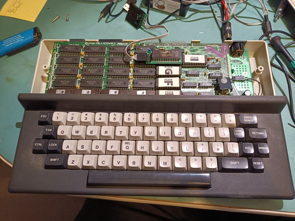
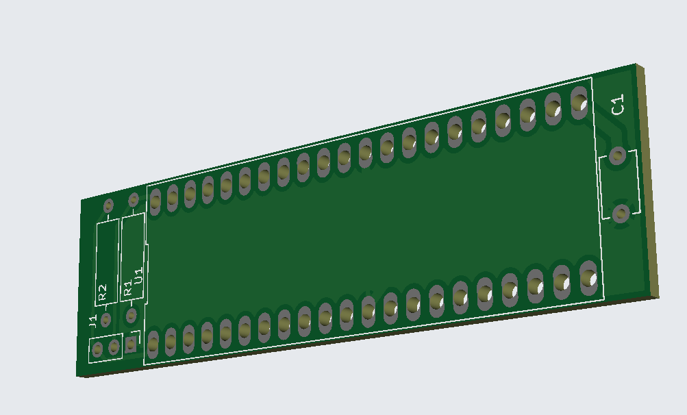
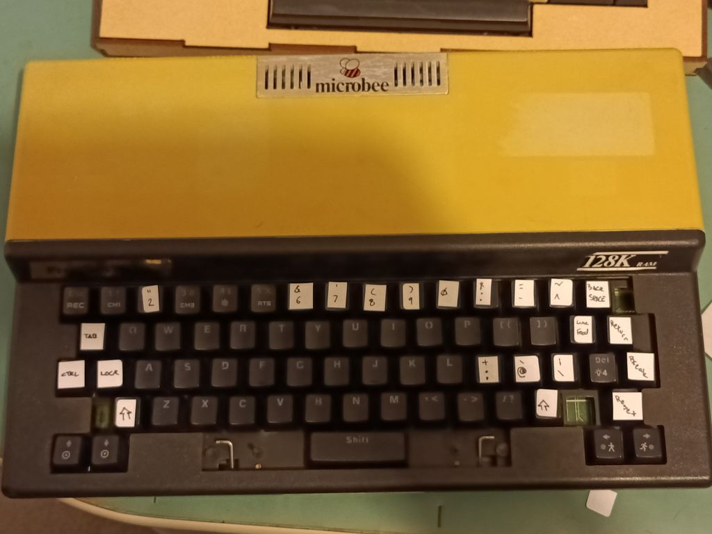
The next revision will fix that bulge at the bottom too. My clearances weren’t perfect.

Microbee Keyboard

This one, well let’s just say I ended up taking a completely different path to the path I planned.

Originally I had been given an “interposer” board (Thanks Brad!) but after several attempts I couldn’t get it to work reliably. To this day, I’m not sure what is wrong with it. I assume I did something wrong, but after the third time I had to desolder all 63 keys to make a correction, I gave up on that path. I’d never managed to get a single key to register, despite checking everything, and finding no obvious issues.

The interposer board. I even managed to lift a trace on it…

I’d wasted too much of Brad’s time, and too much of my own. Time to think laterally…

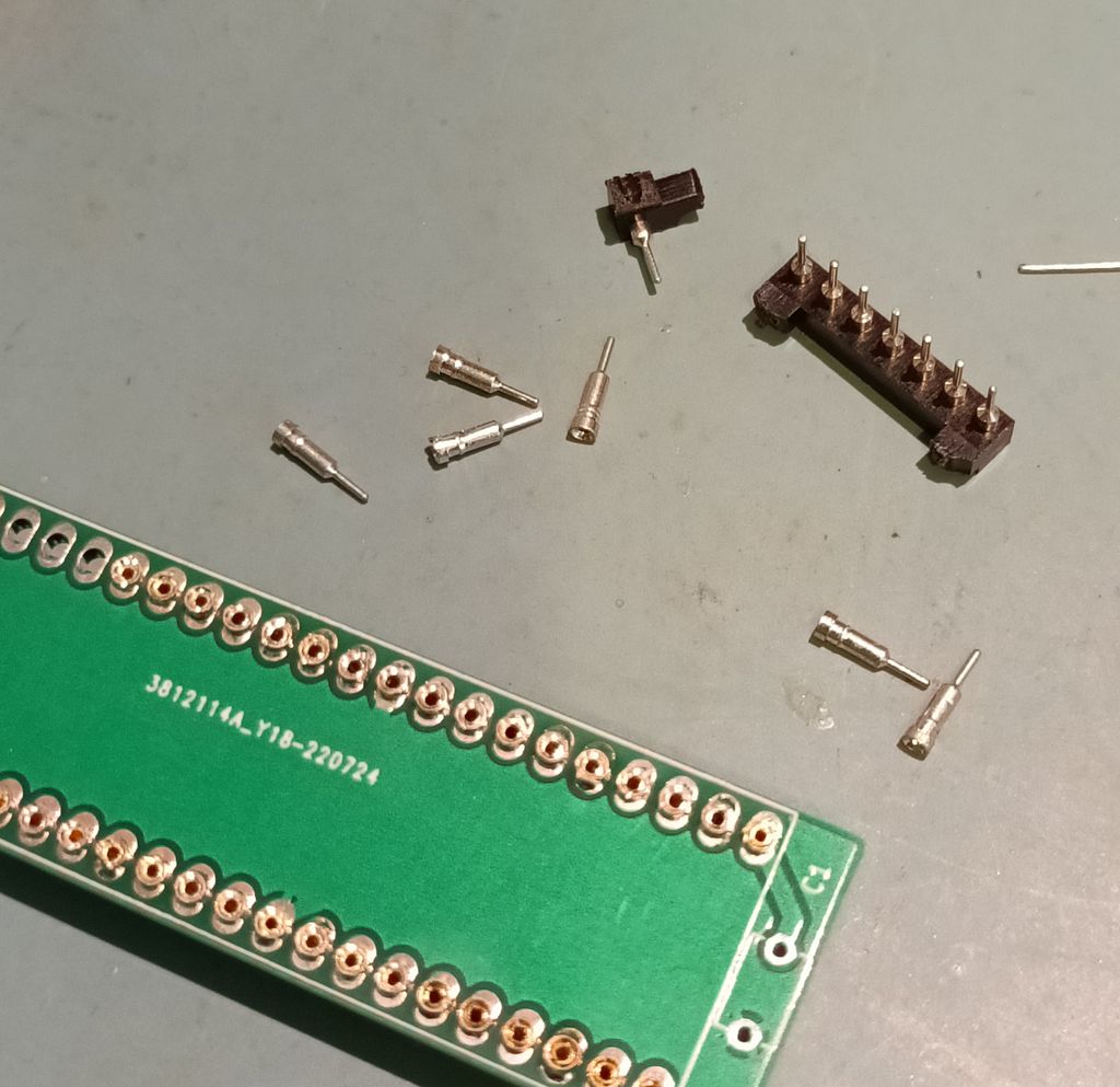
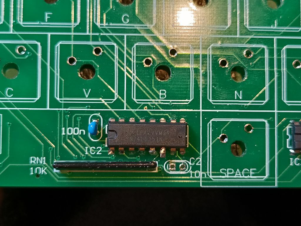
I knew the main PCB was working as if I shorted out the connection holes with a pair of tweezers carefully, keypresses would register. The next step, obviously, was to get the mechanical keys I had (knockoffs of Cherry MX blues) and get them talking to the PCB.

There were several barriers

  1. While the Cherry MX knockoffs (Henceforth referred to as the MX keys) fitted perfectly into the keyboard frame, they didn’t extend below the frame as far as the original keys (Henceforth referred to as the OG keys) which left about a 5mm gap
  2. The MX keys and the OG keys also had a different footprint. The holes on the OG keys were evenly aligned and spaced towards the top of the frame. The holes on MX were offset from each other vertically, and tended towards the right of the frame.
  3. The keystems on the MX keys is a lot narrower than those on the OG keys.

I realised 1 and 2 could be solved with the same solution. 3 was always going to be a problem, and I’d already designed a 3d adapter that would hopefully solve this.

So how do we solve the problem 1 and 2? We extend the legs of the MX keys and bend them to match the OG footprint!

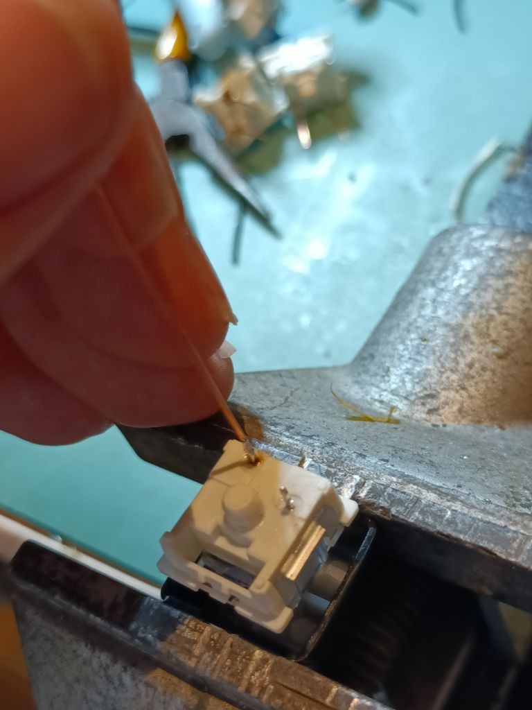
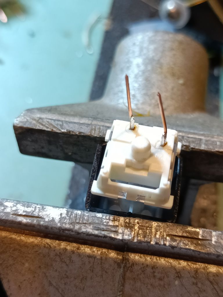
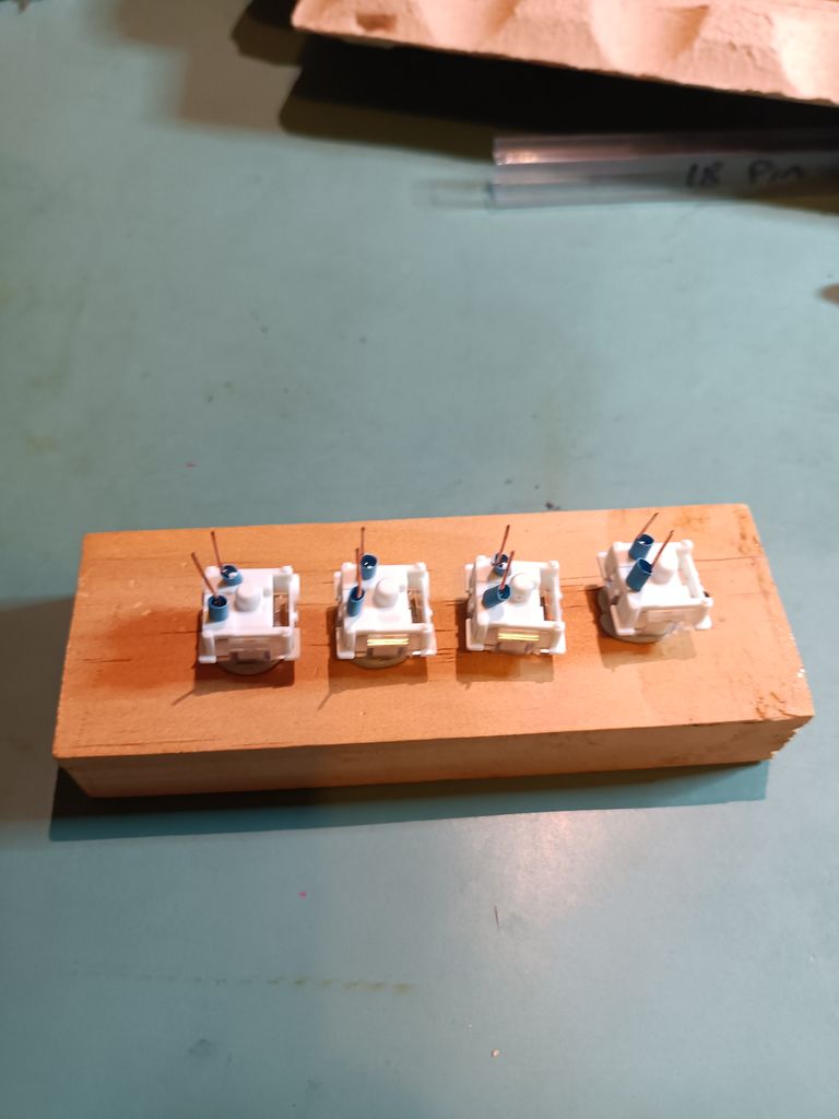
Further thinking and I’d refined it even further. Use solid core wire, as it will keep the bend. wrap the solder joint between the key contact and the wire to provide both electrical insulation as well as to minimise the chance of things “coming apart” as I solder in the switch.

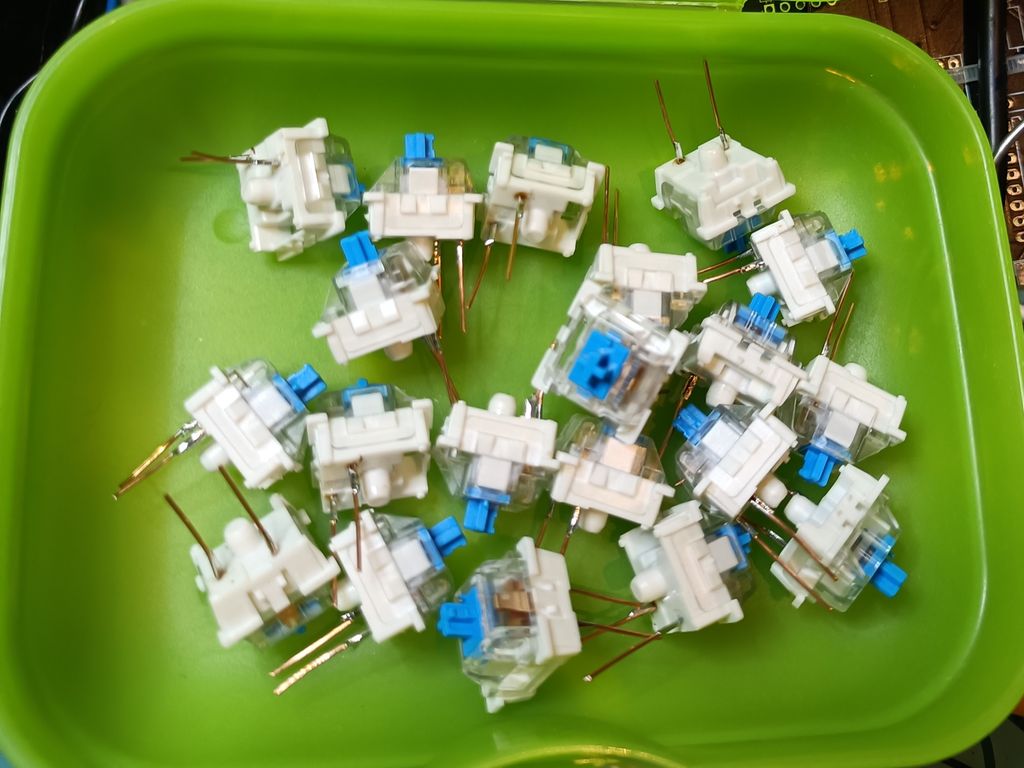
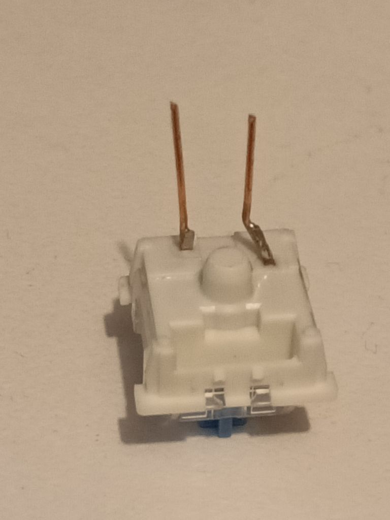
A bit of tweaking and a few attempts and I had this:

No idea what the “artistic burnmark” is behind the switch…

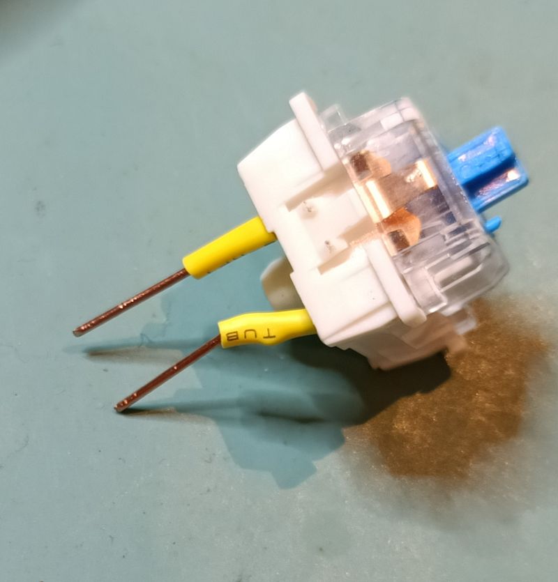
Now repeat another 63 times! (I wanted one spare).

20 down. 44 to go…

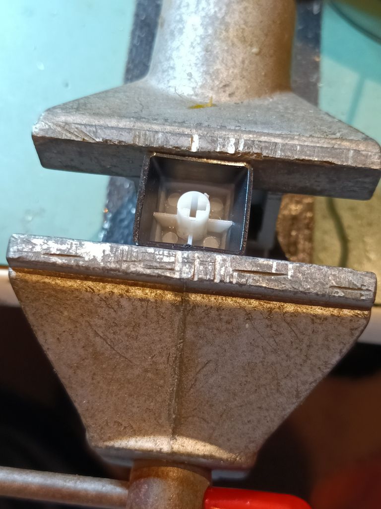
I ended up making two different jigs to simplify things. The first was a suitable keycap off an MX compatible keyboard, inverted and held in a clamp. This allowed me to hold the keys very precisely and aided in soldering in the wire extension legs with minimum swearing. I also used plenty of flux, and tinned both parts of the joint. It went much more smoothly than I expected.


The second was a “bit o wood, holes drilled and a blob of blu tack around each hole”. This allowed me to heatshrink several keys at a time when I reached the heatshrinking stage.

…ali in a row.

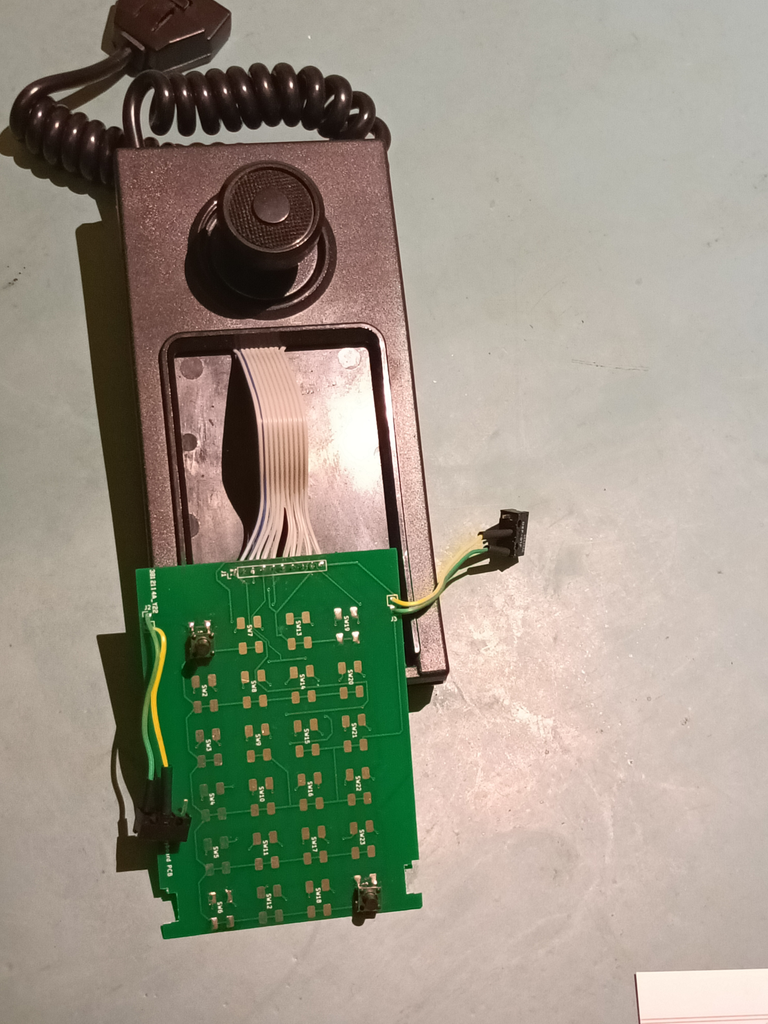
Now my keycaps were ready, and all carefully bent and tested to make sure I had a good fit, the next challenge was to make sure the keyboard frame was held at the right height. If this step failed (And it had failed several times when I was using the interposer PCB) then the case wouldn’t fit properly.

Thankfully I had a “clever” idea, and simply soldered back in four of the OG switches on the four corners of the keyboard. (Conveniently there were even 2 “unused” spots next to the arrow keys, which helped secure the lower half of the keyboard without blocking any “in use” key spots.)

You can see the black OK keys in the corners.

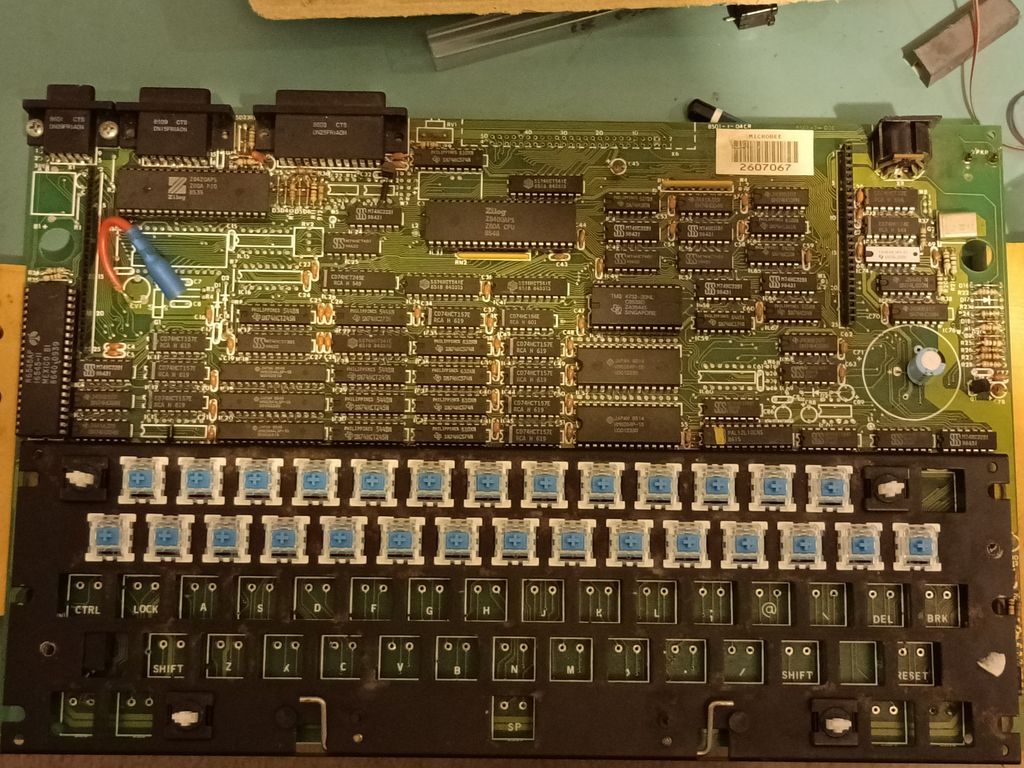
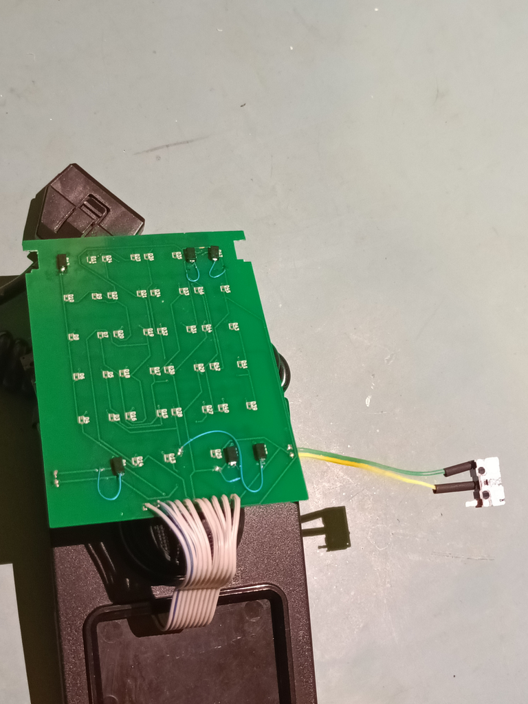
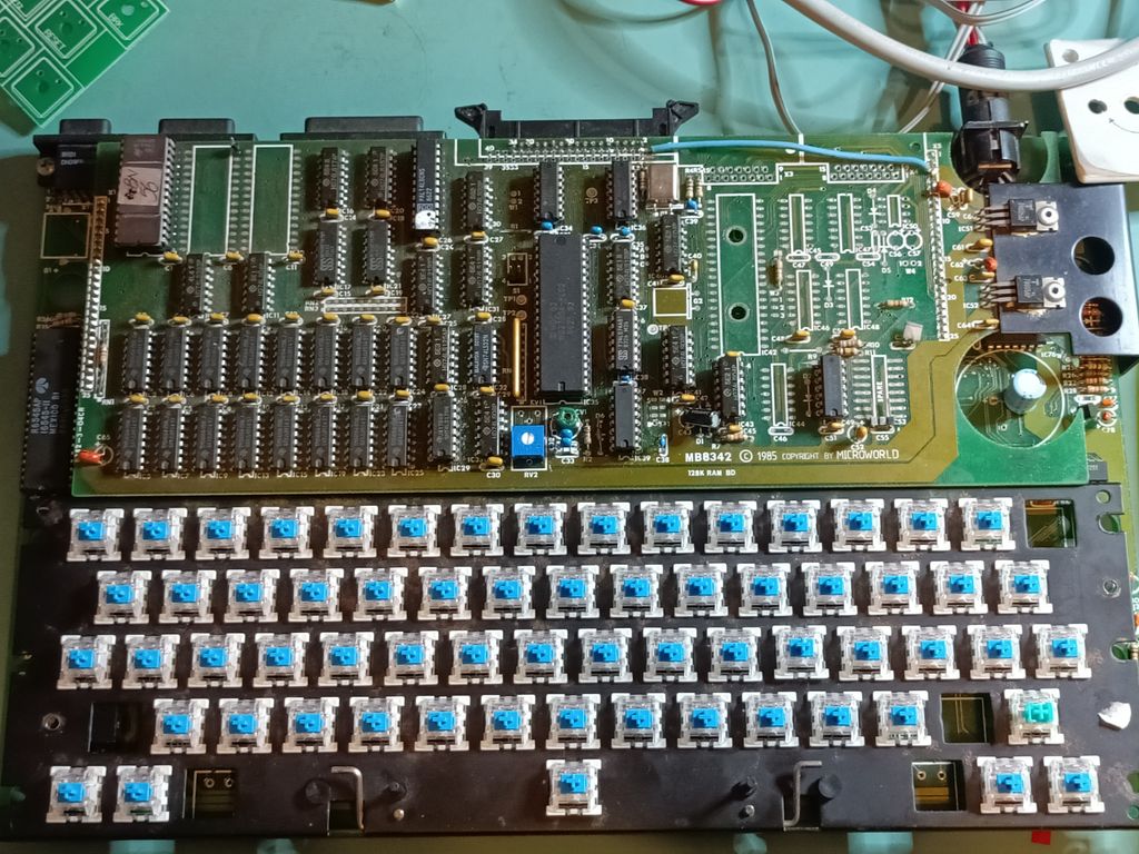
Once those four were in (only soldered by one leg each) I was able to quickly solder in all the rest of the keys in a short time. Once the new keys were in, I desoldered the four OG keys and soldered in the remaining two keys. Everything looked good, but the test was always whether it actually worked or not.

They’re all in. Yes, there are “spaces” for non existent keys. Some are for stabilisers, some are just unused.

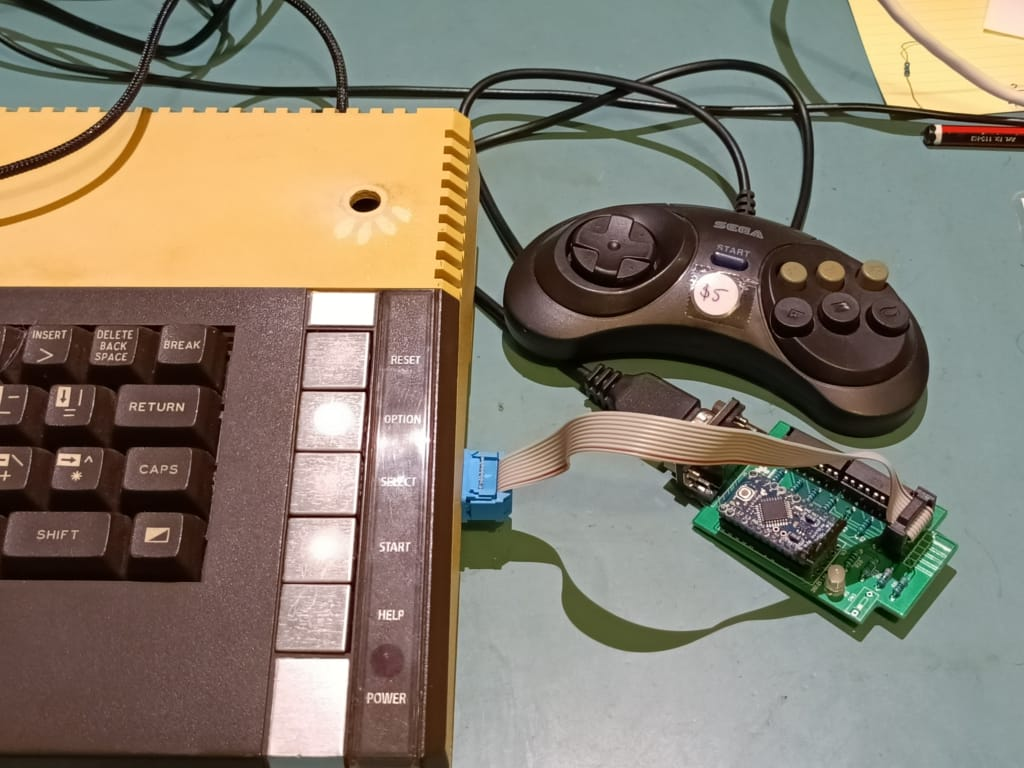
Apprehensively I turned on the system, with my Gotek connected with a virtual disk of Adventure games slotted in.

It asked me to hit a letter to choose a game. I pressed the “a” key, and as hoped, Zork loaded! Even better yet, I was able to then type “open letterbox” followed by “the quick brown fox jumps over the lazy dog”. It worked! All the keys worked!

Typey Typey Workey Workey

I was overjoyed!

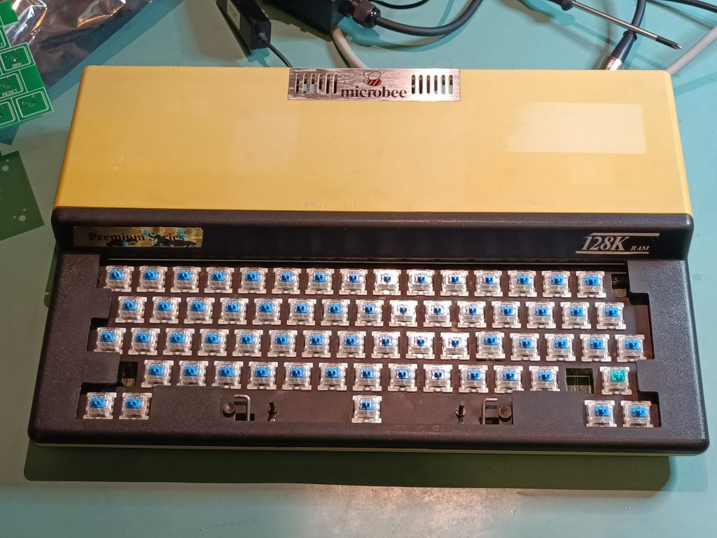
I still need to print out the stem adapters so I can use the original keys. For now I have “borrowed” keys from a mechanical keyboard and stuck them on as a “temporary” solution.

I did this so I’d HAVE to fix the keycaps 😀

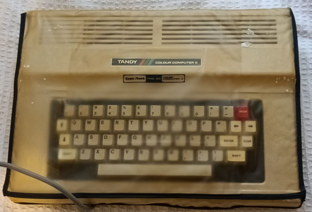
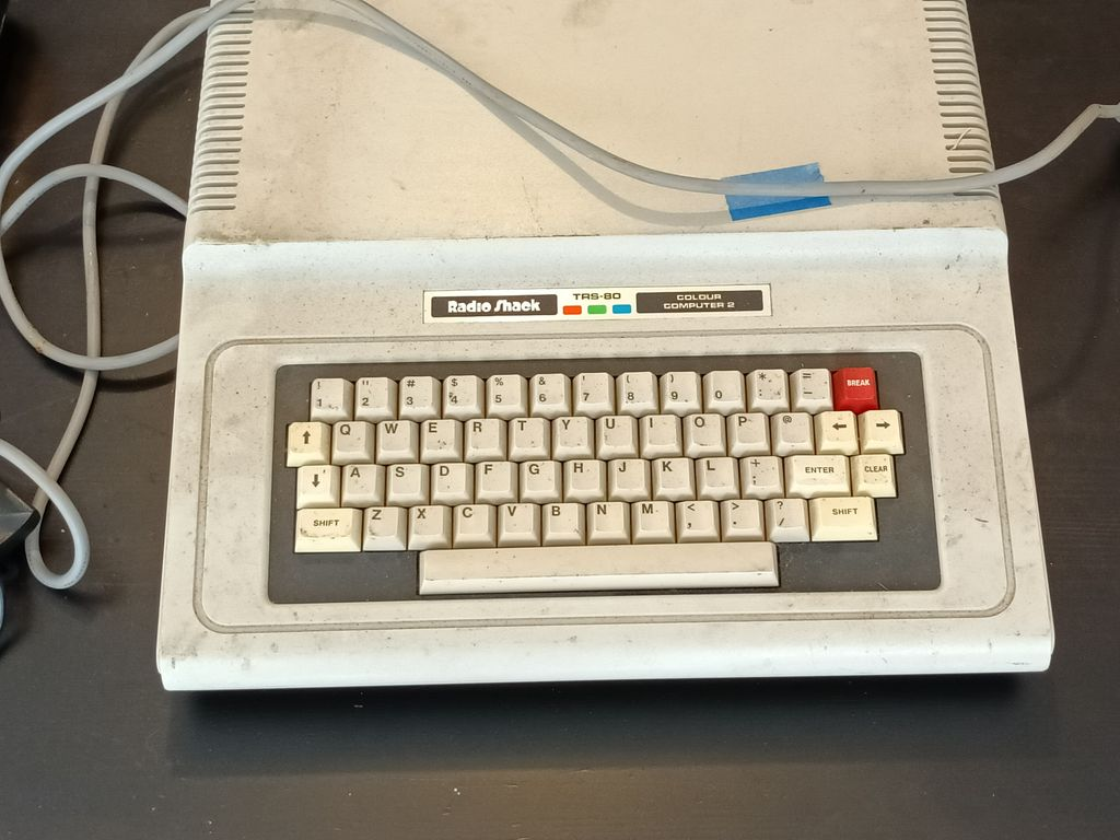
TRS / 80 Color Computer Disk Drive

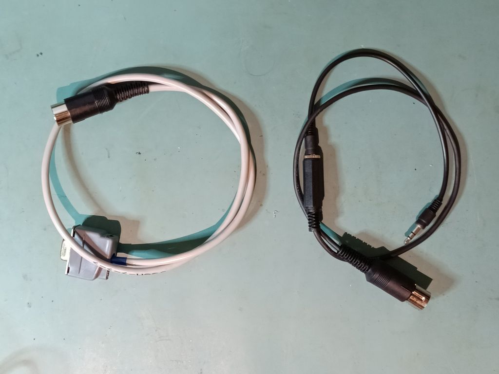
The CoCos have been pretty reliable. It took me a few goes to be able to reliably load software off “tape” to it. (I had made up my own adapter to go from the Tape input to a 3½mm jack so I could use an old mobile phone as a “tape drive”.)

Someone on the CoCo discord suggested I look at DriveWire, which turns out to be a clever piece of software that uses your computer as a “virtual” disk drive with the CoCo. The cable was easy to make, and I had “real” serial ports on my PC to make everything easier.

Linux has made things a smidge more complicated but I’ve worked around most of the issues

DriveWire adapter to the left. Tape adapter to the right.

So far I have played a handful of games. The only painful part is that I have to load the DriveWire software each time I want to play a game, and that takes nearly a minute each time. Not unbearable (hey, I grew up using a Commodore 64 after all) but not exactly “snappy”.

I plan to get DriveWire on a ROM eventually, as well as I have a CoCoSDC on order.

Mega-But was always used to advertise the CoCo. It was like a game from another universe to me as a kid.

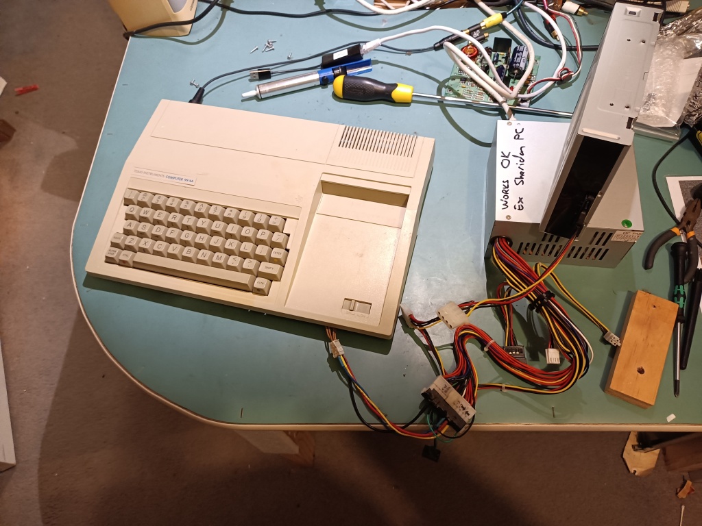
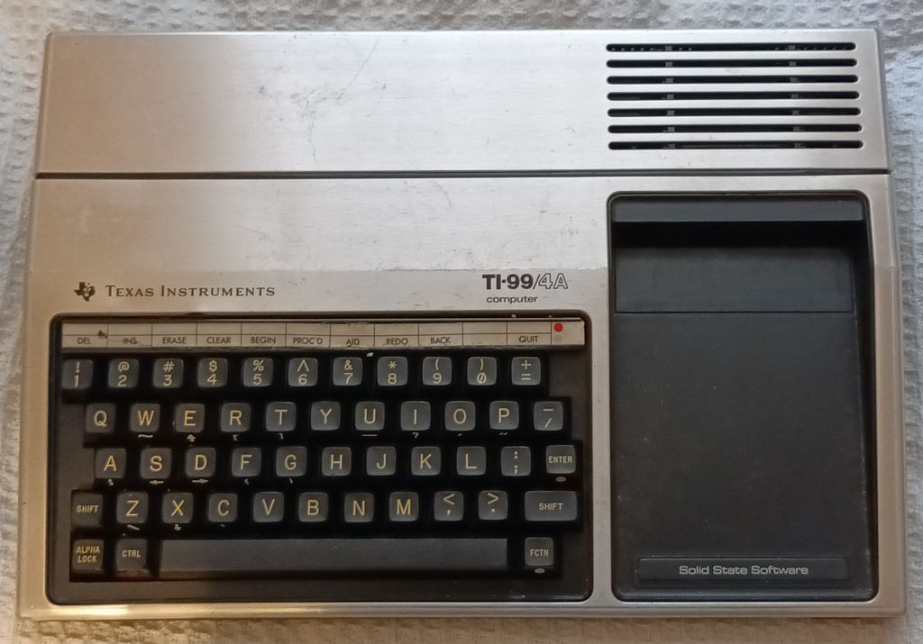
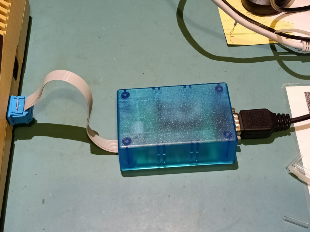
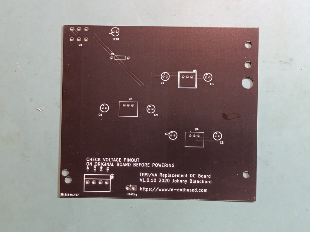
TI 99/4a Power Supply

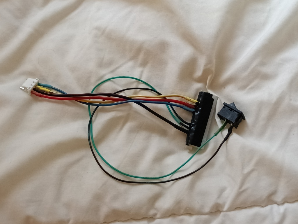
I finally got all the components to make up the power supply boards. These are drop in replacements for the existing internal power board. This ended up being a very easy project with only a handful of components. 12 in total including the power connector. I was able to source everything new except the power switch which I salvaged off the original motherboard.

I failed to take a single picture of the board before I installed it.

I very gingerly and carefully tested at every step. No shorts to ground. OK, power up the board without plugging it in and check voltages are all OK.

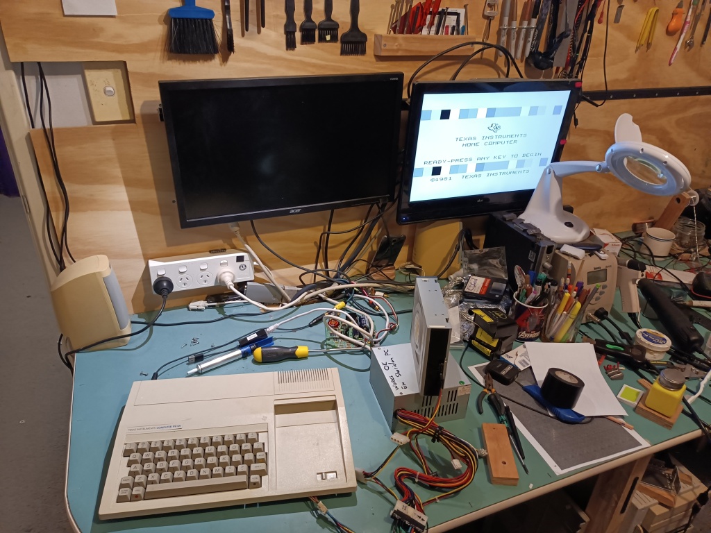
Once I couldn’t find anything else to test I reassembled the TI 99/4a and plugged it in and it worked first go! I was pretty happy, to be honest.

Black and White. You can see the original PSU in the background.

Next up I copied the silhouette of the original power supply socket onto some tin and carefully used my nibbler to cut around the edges to get an nice neat piece to fill the hole where the original sat. It looked really nice, so I carefully drilled a hole for the new PSU connector to come out. Stepping up slowly in drill sizes, I was up to the second last drill bit, when it “bit into” the metal, wrenched it from the pliers I was using to hold it, and promptly munched a great big jagged hole.

There was much swearing.

Version 2 used a piece of an old “rewards” card of some time. Soft enough for me to be able to work easily. Hard enough that

At least I coloured it in black nicely with sharpie.

After a while I noticed some flakiness that I eventually determined was the salvaged switch so a quick disassemble and clean with an ink eraser, and it’s been rock solid since.

I wanted to try one more thing.

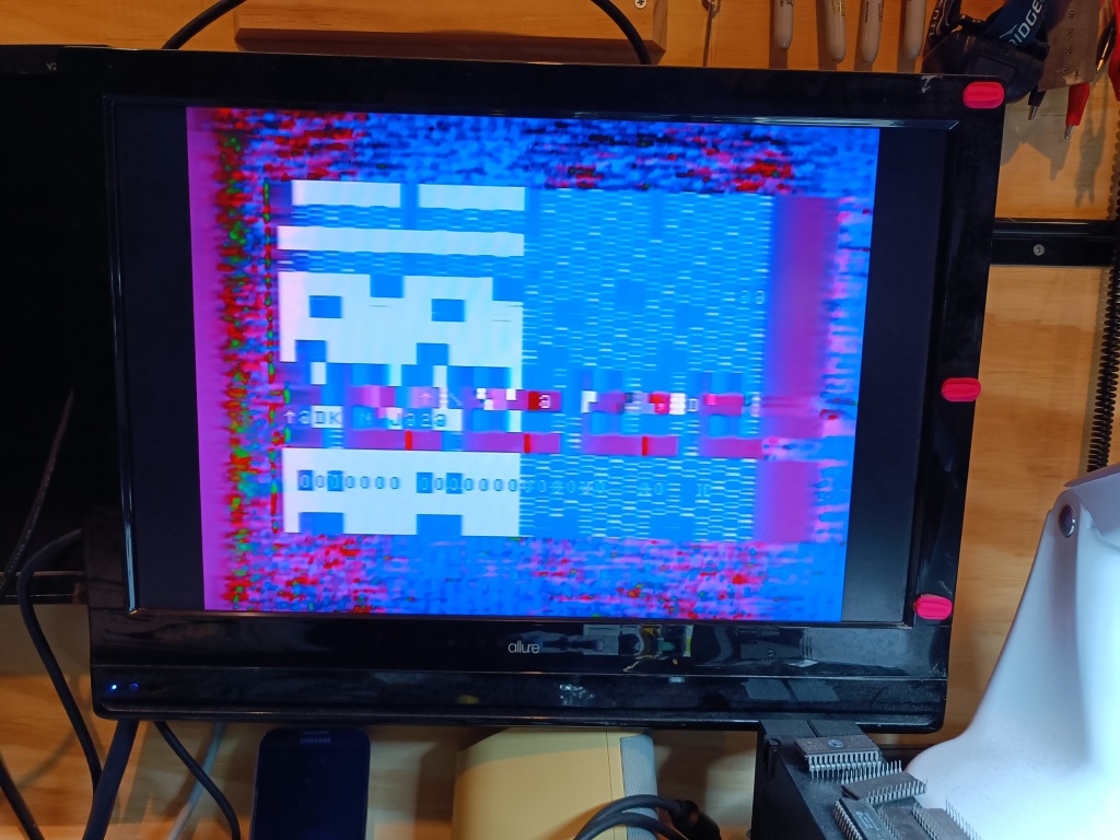
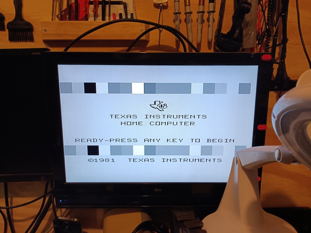
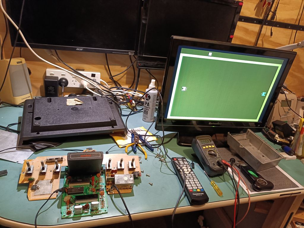
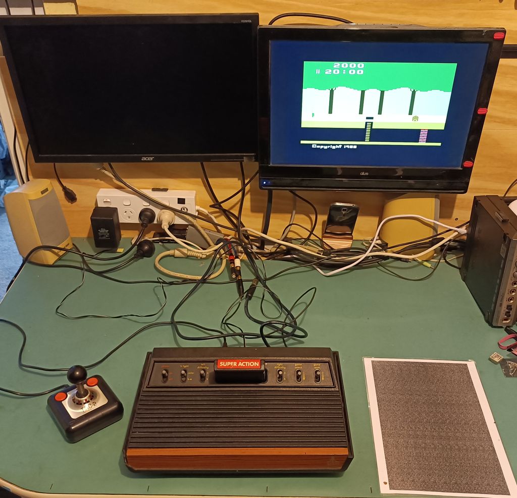
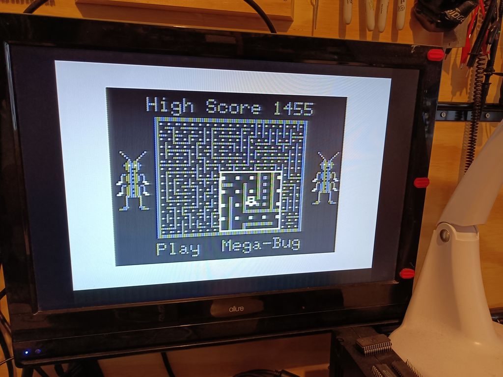
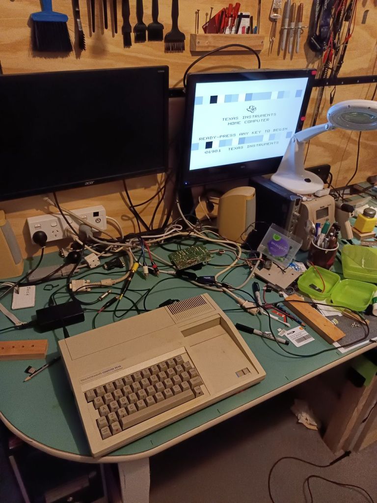
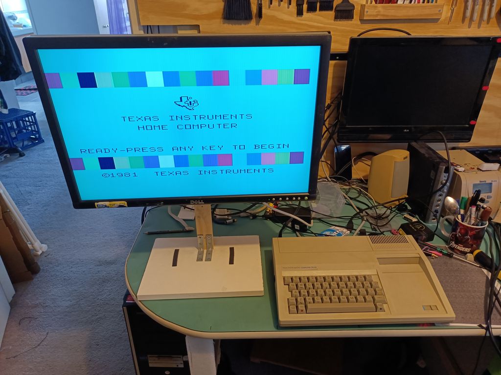
See, as this was a PAL model TI 99/4a, there was no colour directly out of the video port. There were two options: Mod the TI 99/4a to extract RGB colour via a sub board (A mod I may do one day, and I might even test on a CreatiVision) or try and find a monitor that was compatible with the slightly wonky Composite (YPbPr) signal on the video port.

Since I had lots of monitors, I took a punt and made up the appropriate video cable. Worst case, it would still work as a composite signal.

I couldn’t find a Component cable to buy so I just put heatshrink over an old AV cable I had instead.

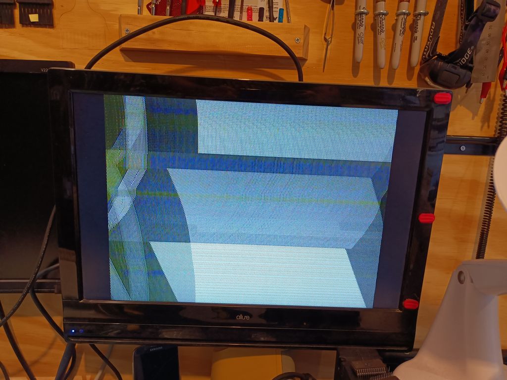
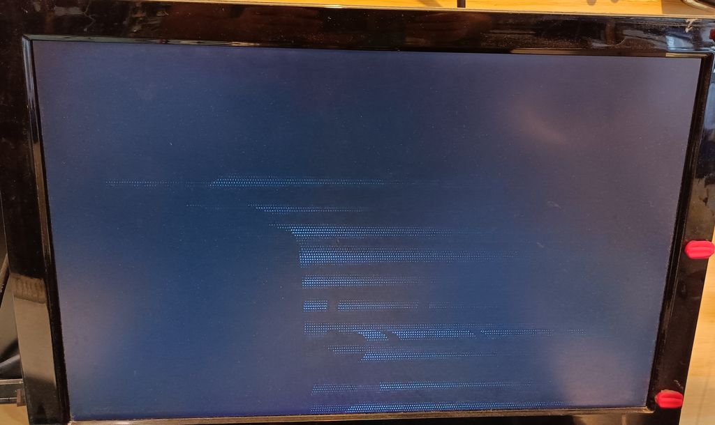
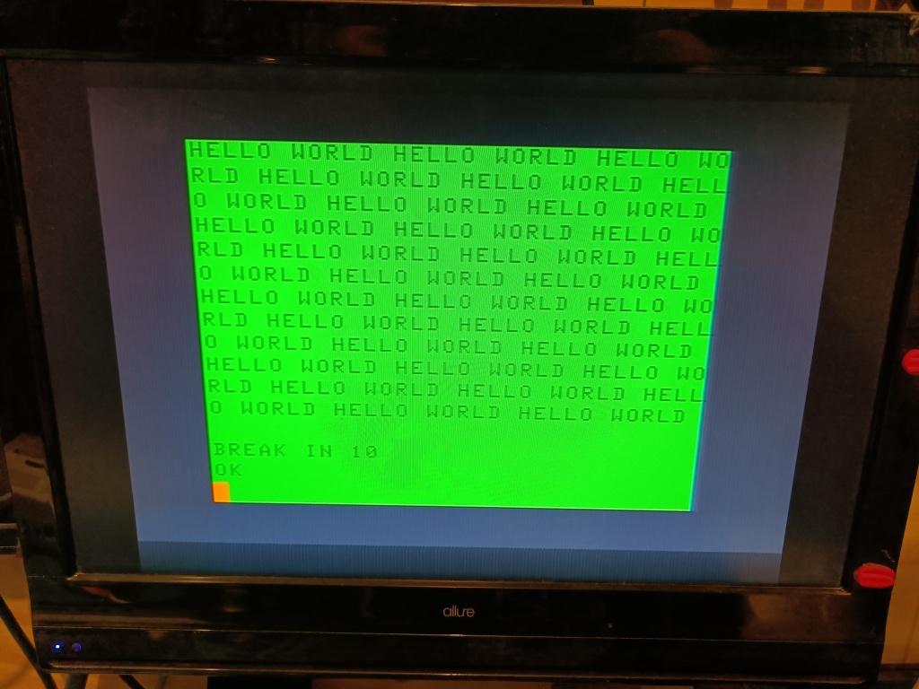
Plugging it into my first TV, I got a brief picture followed by “Invalid Format” on the screen. Same on my second TV. On a whim I tried it with one of my old massive Dell monitors and, to my surprise, I got a rock solid colour image! It does mean I have to use the TI exclusively with that monitor, but I can live with that.

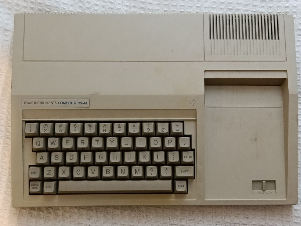
One final addendum. I finally got up the nerve to test the second TI 99/4. It works fine 😀

It’s off to a new home shortly…

Working on the Haul

Well, I have the “haul” of old computers, and I’ve been slowly working through them

TRS-80 CoCo

With the 4 I had, all were using RF, and I knew one worked and one definitely didn’t work. I started by doing an S-Video Mod on the first one I picked up. With 2020 hindsight, this was the wrong move. I should have started with the known good system, but I’m a sucker for punishment and I went off and modded it anyway.

At the end I got this

That ain’t good
That’s even worse.

Not really what I was looking for. I should have started with the system with the known working state, surely?

OK off I go then.

About halfway through constructing the second cable, a suspicion I had with the first cable finally makes me go and check, and yes, the first source I had for SVideo cable order had the luma and chrominanc e pins flipped.

I finish off this system and…

I feel I should start using “HELLORLD” for these thanks to Usagi Electronics.

“Hello World” indeed!

Back to the first system, I fix the pins on the SVideo pigtail I’d made up and…

This is even funkier when animated. Imagine all those colours shimmering through the rainbow.

Still not right. Sigh!

At this point I realised I had an untested CoCo of the same make and model, just missing chips. I populated it from the giant pile of loose chips I had accumulated for these systems.

This time, I was very careful to make sure all the chips I used were all “appropriate” to the system version. I’d been posted a closeup of someone else’s working CoCo 2 of the same model, which meant I was able to fill out all the components without an issue and, despite being RF, it did produce an acceptable system picture and booted to the BASIC prompt.

Right! Now it was time to play the “swap chips” game to see if I could get the already SVideo modded CoCo to work. One by one I swapped over components, and very quickly it came to life. In the end, I’d used two chips that were the wrong revision, and the picture was marginal with two of the 6832 Video Display Processor chips I had, but a third worked perfectly.

In the end I had three working CoCo 2s, with two modded for SVideo out.

TI 99/4A

At the beginning of this I had no idea how to proceed.

I went online and joined several forums, and the overall consensus was: Built a quick and dirty replacement PSU for the system rather than trying to build a transformer. Build a black and white Composite cable, and if things work, start upgrading.

Finding an older ATX PSU with the much needed -5V line intact (They were deprecated from the ATX Standard so most new PSUs don’t have them), I proceeded to carefully make up a cable. I was aided by the voltages being written on the existing PSU inside the TI 99/4A. Also I had all the parts pretty much lying around. Even the connector was modified from one I’d desoldered off a Meanwell PSU I had previously used in a different project.

Even the shrinkwrap is the right colour.

I unhooked the original PSU, plugged in the cable to the ATX PSU and propped everything up carefully and…

The moment of truth… The old CD ROM is extra PSU “ballast load”
Hey! That’s looking good!
Actually, that looks great!
Turns out this is all in lower case, and thus is not recognised.

Right! I have since ordered a replacement PSU board that runs the entire thing off a single 18V PSU from an old laptop.

System 80

The System 80 has an enhanced OS inside it which is awesome. I have replaced the drive belt on the tapedeck, but I’m not getting correct volume levels out of it. I’m researching what to do next with that. I even fixed up a seperate tape deck so I could use it to record WAV files to tape off my computer.

Retro Chip Tester Pro.

After four different attempts, an AVRISP I had borrowed from a work colleague finally let me program the Retro Chip tester Pro.

I’ve used it to test hundreds of ICs in just a few days. Turns out I have a LOT of working 4116 RAM.

The Long Haul

So recently I managed to participate in an exciting retro-computing “thing” in the form of clearing and organising a seatainer full of old computers and peripherals. While most were not systems I was interested in (So many dead printers, for instance), there were some gems that I took home, as did my fellow participant.

This pile was officially a discards file, so everything we took was saved from the trash-heap, and the collection was a lot neater (And less likely to topple over, crushing unsuspecting passers by) so hopefully others in our group will be able to get gems as well.

So what did I get? Well, I actually managed to get enough to complete my core collection.

I’ve always wanted to have enough computers that I had a representative of all the major 8 and 16 bit systems. I’d already got Commodore, Sinclair, Amstrad and Acorn systems, covering my European systems pretty much completely. Next I wanted to get some North American systems under my belt, and that meant Texas Instruments and Tandy – Radio Shack systems.

I’d already got a non working TRS-80 Colour Computer 2 (AKA the CoCo), so one of the things I was tracking was a different CoCo as I was having problems with the one I’d collected.

I was able to pull out three more CoCos, in two different variants, one in box.

Now I had a CoCo, I had been thinking about what I was missing. Now realistically there were two more systems left to collect. One was a “classic” TRS-80 system, either the Model 1 or one of the later variants such as the Model 3, and a Texas Instruments TI 99/4A system, famously “destroyed” by Jack Tramiel as revenge for TI trying to drive him out of the Calculator market.

As a result, while going through the pile, I was “keeping my eyes open” and oh boy did I strike paydirt! (And the word “dirt” can be emphasised here. There was a lot of grime on these systems)

As we went through, we kept finding boxes of systems and peripherals. Stuff just kept coming out, layer after layer. My fellow participant got several new and interesting systems, including a lovely Tandy 1000, a pair of MSX systems, A BBC Master Compact, a Sharp MZ 700 (A system I know nothing about) and a bunch of Commodore 64 peripherals.

Me? I pulled out this lot:

Long picture is loooong.
  • 3 “Atari” style joysticks. 2 CX 40 clones and a Star Cursor, alas with the cover vinyl torn off.
  • A Commodore Music Maker keyboard for the C64. It’s got damaged keys so I’ll need to fix it.
  • A VZ200 tape deck I have set aside for a fellow collector I know is into the VZ family.
  • 2 different Amiga external floppy drives. I have gone from none to 3 in just under a year.
  • Three different TRS-80 Colour Computer 2s, one in box! More on them later.
  • A Commodore Plus 4. More details below.
  • A BBC Model B. Again, I’ll detail more below.
  • A Dick Smith System 80. This is a TRS-80 Model 1 clone. (🗸). Yep, more below.
  • Two TI-99/4A computers. One in Black and Silver and one in Beige. (🗸)
I didn’t bother taking a photo of the CX40 clones.
While complete, the black keys have become brittle and snapped off

That’s right, I have all the systems now! Let’s see if they work.

TRS-80 Colour Computer 2

That cover… “Dead! Wrapped in plastic!

Now I already had one here that I was having problems recovering related to different compatibilities with chips. While I was collecting CoCos, I also grabbed a “stash” of spare components to fit the systems, as I knew that the socketed chips had been stripped from these CoCos. First up I grabbed the one in box. It was also in a protective cover, which had unfortunately reacted with the surface. I checked it inside, and to my surprise, all the chips were intact. The power supply looked to be in reasonable shape, so I pulgged it in and powered it up and after tuning in the RF on my TV I was able to get a picture. Excellent!

Currently I’m still working on the other 3, to see if I can get any more working.

Commodore Plus 4

An elegant computer for a more civilized age.

Working on the plus 4, the first issue I hit was that the power supply connector is a hideously non-standard 4 pin square DIN. After trying to find a new one for a reasonable price, and a lot of online research, I went down the same course as many people before me, and replaced it with the connector from a Commodore C64. The mounting holes are mostly matching and the power ins are in the same place, so it wasn’t too much of a drama. After some mucking around (and finding my C64 PSU had a ground pin missing) I was able to power up the system. Unfortunately I just get a black screen. I’ll need to diagnose further as these are quirky little systems with some unique games. Hopefully it’s not the custom chips as they’re practically unobtanium these days.

Acorn BBC Micro model B

This is after I cleaned it… Twice.

The first thing I needed to do with this system was clean off where the feet had literally rotted into black sticky goo. Once done, I was worried the beeb would have the infamous “Rifa” X2 capacitors inside it, so I stripped it back and checked the power supply before I worked on it. While it turns out this model didn’t have Rifa X2 caps, it did have this crusty boi inside it…

That ain’t right!

I replaced it and powered it up and it boots. The power supply is making an ominous buzzing noise so I need to investigate that further.

I also determined it has a “bonus” EdWord ROM inside, as well as a disk controller, so this will be a nice system for playing classic BBC games.

Dick Smith System 80

It’s hard to get an idea of scale for this system.

Aka the “chonky” system! This is simply MASSIVE. It’s as deep as a Commodore 64 is wide, and almost as wide as the Amstrad CPC 464 is wide. It’s taller than both!

Opening up this one revealed a very neat three board system with no major surprises. It had a monitor port, so I quickly made up a suitable monitor cable and it booted right up! Awesome!

Some other systems for scale.

The keyboard seems to work and I was able to type the usual “Hello World!” message. It’s going to be interesting to see what software I can run on these as they’re only “mostly compatible” with the TRS/80. I’m also curious about what peripherals are available, as it would be great to get a disk drive and a 32K expansion.

TI-99/4A

Two of them, no less! I’ve been working on getting proper power into, and proper video out of these since I got them.

They use an unusual internal power supply with two AC inputs. One is 18vAC and one is 8.5vAC, so I assume some sort of center tapped transformer was used. To test I plan to use an old ATX power supply and bypass the internal regulator and go straight to the 3 internal power rails (+5, +12, -5)

I also need video out as these don’t have composite or RF. Instead they have a modified Component signal. I’ll tap out of that to get composite initially, and down the track I’ll see if I can tweak the video to get a component picture I can use with my TV/Monitor. That can wait until I confirm the system is actually functioning.

So now I have “all of them”, I’m actually in a position where I’ll probably thin out some of my collection. There are already several systems I’m thinking hard about selling to raise funds to upgrade the systems I want to keep.

Argh!

So far, I have broken / failed to fix:

  • The Microbee keyboard for the Premium 128k. I’ve lifted a trace while trying to diagnose what went wrong with it. I need to remove a capacitor from it but i’m not entirely sure that is the problem.
  • The Retro Chip Tester Pro. The programmer I used for it failed to program it properly. I need to find a different programmer.
  • The CoCo. It has a missing chip, and I ordered what I thought was the replacement. It wasn’t the right chip.

Some days this hobby can be a bit depressing…

Fun with “Stuff”

I do apologise that I haven’t been updating as much as I could. There’s been personal things going on in the background that have slowed my output down.

Atari 2600

The replacement 6507 CPUs arrived and after hitting a dud, my second chip worked fine. This is why you always buy a couple.

I did hit an odd issue pretty much straight away. The system would work when out of the case, on the bench, but not with the case on, which was odd. It took me a while to work out what was going on. With the case on, slight pressure from the bevel was pushed on the power lead I’d made up. (It’s a standard 9V PSU 750mA, tip positive with a 3.5mm audio jack connector)

This is obviously before I put the case on. Combat!

I’d already rebuilt the socket on the board, but with the pressure from the case, it was enough to lever the tip away from the internal contact. Going through my parts bin, I was able to find an audio jack on an old tape drive cable for my Acorn Electron that had a much thinner outer shell section, and switching over, it worked fine with the case on.

After I got that working, I decided I needed to get rid of RF. It would be a pain to have to use RF with the television I wanted to connect to, so I looked around for a solution and found an excellent writeup on using S-Video with the unit.

The article here on NFG Games was simple, and easy to understand. The only complicating element was the difference between NTSC and PAL TIA chips, which I was able to discern with aid of a multimeter and the guide to the pinout differences I found here on Atari Age.

I designed up the board using a couple of different tools. By the time I was onto my third draft, I had reverted to using graph paper to finalise things and managed to get everything I wanted into a small footprint.

I ended up having to buy some bits and pieces from a local hardware store, most notably resistors, as it used some tuned values. Almost everything else I had on hand.

Once I had everything together, I assembled the board on some veroboard prototyping board.

It ended up to be quite a compact design.
The back, with many cuts to break the veroboard tracks up into electrical islands. I used my multimeter extensively through the process to make sure there were no shorts between islands.

After that, I spent the time finding all the appropriate places to tap for my various signals on the back of the board. Much checking went in to make sure I had the correct connection spot for everything.

Check. Check again. Check a third time.

Finally it was time, so I plugged in the cables and tested it and…

It works!

I had SVideo! This system now lives in my console wall and gets broken out for regular games of Space Invaders.

Sega MegaCD

Well, it just works with burned CDs, so media turned out to be a non issue. I need another PSU for this unit, and then it can join the 2600 in the console wall.

Saaaygah!

Omega MSX2

Finally got all my ducks in a row and ordered the acrylic to start cutting some cases. The Omega MSX2 now has a proper case!

There’s also most of a Microbee case in there, but I need to get a contrasting colour for the keyboard section.
It lives and the clear case and purple PCB looks stunning.

I did end up having to remove all my heatsinks from the chips as the keyboard ends up sitting too close to the top of the motherboard.

Really happy with the way this turned out.

TRS-80 CoCo2

I’m having some problems with this one. I seem to have a reasonably obscure revision of the motherboard, so I have had problems sourcing some chips.

I’ll get there in the end I’m sure. For now, I wait.

A New Pickup

Picked up this cutie from a fate worse than death. It worked as soon as I stuck batteries in it.

It even does a tinny rendition of the PacMan theme. Plays quite well too!

It needs some work as the screen surface has some cable burn but I’m hoping with the right polish, that I’ll be able to bring it back to a nicer finish.

Quick Update on Multiple Projects

I’ll try and keep this informal this time 🙂

The Atari 2600 seems to have a bad 6507 CPU. The voltage drops to zero when it’s inserted. I have a replacement on its way

Of the CreatiVisons, I managed to get one to boot fine and one just gives black screens. The tape drive works. The port expander works after a clean of all the connectors and having the LED changed out.

The Sega CD boots fine. Just trying to find some media for it now.

The Microbee mostly works. It seems to have some high RAM issues that I still need to work on. Also the keyboard is dead, bar 8 keys. I have a kit to convert it from using the horrible, custom keys to using much more useable Cherry MX keys, so I have a batch of them on the way.

No movement on the CoCo. I hope to get all the missing chips later this month.

The Arduino Joystick doodad now has autofire, which is very nice. I need to do some more code on it to add additional buttons for Atari systems. They’re plumbed in electronically but not coded in yet.

I’ve had a bit of a setback on the joysticks for the CreatiVision insomuch as my attempts to combine PCBs to keep the cost down was rejected. I may need to try a different PCB house.

The Big Haul

So on the weekend, as part of a local organisation, I did some volunteer work. In return I got some old systems donated to me. And what a donation it was!

While none of this equipment is in what I would call a “working state”, it’s all fixable and it’s all super interesting.

First up there was this 6 switch light Atari 2600.

Not sure what to make of the SpectraVideo keyboard addons.

As you can see it came with a library of games. Unfortunately it didn’t come with any power supply, and it doesn’t appear to power on. It’s hard to tell with RF systems at the best of times.

The black one with the Cash Converters logo is simply labelled “Atari Game”

I’ll need to open it up, do some basic checking on all the usual things (Voltages, are we getting sane signals on the bus, that kind of thing) as this would be a classic to get working again.

Next up was not one, but two CreatiVision variants, with heaps of addons. One is a genuine CreatiVision, complete with plastic protecting the logo, and the second is a Hanimex Rameses, which is a lovely looking unit!

CreatiVision branded CreatiVision
Can you smell that 80s brown?

They came with 4 of the controllers I’ve been working on so much, a bunch of cartridges (Not so useful in this age of MultiCarts), a mostly complete “full” keyboard, a tape deck and a port expander. Awesome!

Unfortunately both were missing the power bricks. Oh well. I can always make one of those. I have not yet tested them.

After that was the TRS/80 – CoCo 2. This one has had all the custom chips removed, but I have located them and will get them back in a few weeks. This is a system I know nothing about. I look forward to getting acquainted with it more

I have cleaned it since I took the photo
Thankfully I know where all those missing chips are 😀

Finally was a Microbee 128k premium. I’d been wanting a premium from before I built my 128k disk system.

Also cleaned up since. I took off the Ca$h Converters sticker.

The unit, inside, looks spotless. It currently boots the the disk command prompt and no further. Another one for diagnosis. Plenty of things for me to look at with it 🙂

All that space I cleared in my shelves the other week? Gone! Not that I’m complaining 🙂

Finally there was a Sega MegaCD II to go with my Sega MegaDrive. Again, no power supply, and I haven’t even tried powering this one on.

For some reason, in among the Atari carts was an Expert Cartridge for the c64 and a pair of Atari 7800 controllers.

Update on all the PCBs

So remember all those PCBs I ordered?

Let’s break down what worked and what didn’t.

What Worked

So first up, both my ROM adapters worked without a problem.

So we now have a Low Profile Amiga ROM switcher and a Low Profile Microbee ROM switcher. Both built around using turned pins to keep the profile low.

I have one of these in my Microbee PC 85
This is the AmigaROM being assembled.

Excellent!

What Didn’t Work

The Amiga Front Panel had all sorts of odd wiring issues. I redid the circuit, compressing it slightly so it should now qualify for “cheap” construction prices at most board houses. I need to buy some components to check for fit before I order.

I think it was mostly transcription issues going between multiple revisions of the same basic circuit. I also missed a few resistors. Turns out those PS/2 to USB adapters do have some passives in them. To wit a pair of 4.7k resistors between GND and the two data lines. Redone now. I need to check some components for fit, and I’ll be ready to order again.

Yeah, this is “parts only” now.

What “Sort Of” Worked

First the one that “Would have worked if I’d used the right footprint for a component, used the correct sockets and if I’d annotated the schematic with the right resistors…

The ArduJoyAdapter looks like it needs a mild respin to work perfectly 🙂

With a bit of bodging, (I managed to somehow find the wrong footprint size for the Opto Isolators. D’oh!) by stretching out the legs of the sockets and carefully bending (And promptly putting them 180 degrees out) and pulling two pins out of each socket (Because I’d been supplied with the wrong sockets, and I couldn’t be bothered driving 20 minutes each way to swap them, so I just shortened them) I was able to mount the OptoIsolators…

It didn’t work.

After much checking and some eventual realisation of various compounded errors, I managed to get the opto isolators in the right way… and it still didn’t work.

Confused, I pulled out my Oscilloscope and set it up. I could see a suitable signal going into the opto isolators, but not coming out. Then it clicked. I was at 1 volt per division on my ‘scope and was barely measuring 2 volts of peak into the opto isolators.

What?

I had breadboarded the whole thing so I checked the one thing that could be impacting the outputs, the resistors I had inline to protect the inputs. On the PCB I had 10KΩ and on the breadboard was 1KΩ. Yep, that’d do it, being out by a factor of 10.

I desoldered the resistors and dropped in suitable replacements and it started working, which was awesome. The next step for that project is I need to program in more functionality. I want to add an autofire option, as well as one or two more modes. There’s an LED there which supports 3 different colours, so that’s not too much of an ask.

That cable perfectly hides a multitude of sins.
Here it is in a nice jiffy box. The board is designed to drop in. It needs a minor tweak to be a snug fit.

What also “Sort Of” Worked

C’mon, I know you have all been wondering how that abomination of a joystick went. The one with 4 different boards?

Well, it worked, at least well enough to prove the concept.

What went wrong? Well…

  • Traces that go nowhere. Pin 10 simply vanished off to a dead end between the bottom board and the top board.
  • Footprints for components that are 90 degrees out, leading to buttons that are “always on”.
  • Pin connections that are backwards on their markings but are correct otherwise. (If you solder the connection backwards to the markings, it works)
  • Connections that are too far away from the edge. It causes clashes between solder and the rest of the design.
  • Places where the PCB doesn’t allow for penetrations of things like mounting screws and alignment pins
  • Buttons that are in the wrong place.
  • Buttons that are misaligned.
  • A major section that is 90 degrees off. This means that up on the joystick is actually left.
  • I couldn’t get the right diodes on the day so I had to wire in ones that were several times larger than what I had designed for.

Despite all that, it actually worked when I’d laid in enough bodges. I was even able to play several different games, and proved all the “leaps of faith” I’d made in the design were all correct. Of course now I have to do a brand new version of the boards. Should be fun!

Bodged in buttons all over the place.
Bodged in diodes.

Assembling the Microbee MultiROM

EDIT: Important Note! PLEASE READ FIRST!

I made a mistake in my assembly pictures. I have assembled this board upside down! It works if you solder everything to the correct side. Don’t be an idiot like me! Solder so the credits face the underside of the PCB not the top.

So I have finally got a design for a “MultiROM” ROM changer suitable for use with the PC 85, capable of fitting in a standard case in the ROM H position at IC 22.

https://github.com/cheshirenoir/BeeMultiRom

Assembling these is a little non standard so here’s a guide.

You will need:

If your pins are in a socket or strip, use a sharp set of cutters and cut them out of their housing. These should drop right into the PCB in the wide holes. Fill all the wide holes.

Here I am breaking up sockets. I have stopped using this type so I have plenty to spare. NOTE PCB is upside down!

Once you have filled all the wide holes, insert the spare socket into the top of the turned pins. This will aid in soldering.

Ignore the “extra” pin.

Flip the board over and solder in all the pins. Remove the socket once complete. If your socket isn’t as long as your pins, you’ll need to add more pins and move the socket.

Once all the pins are soldered in, cut the thin part of the legs off them. Yes, it feels criminal, but we’re using these as sockets, not as pins.

Next we solder in the header strip in the next row of holes, poking down. If you’re using the same strip as me, the default length will be fine. If you’re using something else, be careful with your lengths. If you make them too long, you won’t have enough room to close the lid. Too short and you might hit the socket.

The rest of the components can be added in now. Don’t forget the resistor pack has a polarity. Make sure the dot matches the square pin.

Note the square pin for the Resistor array. NOTE PCB is upside down!

Add your 27C2001 ROM in after programming in images. You have 16 x 16k ROM images in there. Or 32 x 8k ROM images. Or a mix, as long as you keep everything aligned to 16k boundaries. (If you have 8k ROMs, they can be accessed by either PAK4 or PAK12 commands. If you have 16k ROMs, they can be accessed by PAK4)

Finally the bit I have to leave a bit open. This is the hex encoder. There are SO many options here. I’ve tried this and this. Neither is perfect. The first feels flimsy. The second only supports 10 positions, and is too big to actually fit in the case. Either way, you connect the “common” pin of your encoder to pin 1 and 2-5 to the remaining pins. You could probably even rig up a 4 way DIP switch by wiring all the pins on one side together then to pin 1 on the connector. Then connect the other side to pins 2-5.

I am currently using the second encoder option.

Not a Soldering Iron in Sight

Updates

Starting with an update on existing projects, I have the Amiga MIDI project working. I’d accidently crossed the input and output lines on the MAX2323 chip. A quick bodle later and it was working. It’s now corrected in the master PCB.

Bodge wires ahoy.

I also have permission from Grzegorz Kraszewski to release my version. That was very kind of them. Please note ALL support for my version is through me. If you want a better MIDI device than mine, go and buy theirs. It’s much smaller and does MIDI IN too!

MIDI playing from a free player. Haven’t yet got MIDI working in any games.

I also purchased some proper IDE to CF adapters from RetroKit, who was kind enough to hand deliver them to me. Helps we work across the road from each other :-D. These were able to finally solve all my IDE issues with the Amiga 600. It’s much neater in there now.

I also finally got around to testing the IDE Buffer board for shorts.
It uses really small components, so checking is a challenge, but I wanted to make sure I had no shorts on adjacent pins.
Unfortunately I did have a short on two pins.
I inspected carefully and it looked fine but the two pins were definitely shorted.
In desperation I checked the schematic… The two pins are both pulled to ground. They’re supposed to be “shorted” together

Oops!

This will get installed in my Amiga 1200, when it’s finished.

PCBs

Onto what I spent most of the last fortnight working on: PCBs!

I use KiCAD a lot these days. I regularly design new circuits and systems. I’m not very good at basic electronics, but transcribing a schematic and generating a PCB, I am getting much better at. This week I ordered no less than 8 different PCBs and designed a ninth, just for giggles. More on that later.

PCB 1 was a new spin of my Amiga MultiROM adapter, designed to take a 27C160 for four different ROM images. Not much to this one. My last spin almost worked. I’ve really only enlarged the pin holes slightly.

PCB 2 is a board for my MegaDrive to Atari joystick. I’ve designed it to fit inside a standard jiffy box from Jaycar. Once it’s done, assuming it works, I’ll be programming in extra features like auto fires and step modes. It’s also got a programmable 3 colour LED now, and a switch so I can change it from Atari 2 button to Amiga 2 button. I’ll probably hard code each adapter to be either Amiga or Atari, rather than switching them.

PCB 3 is a replacement for three different PCBs I’d designed for my Amiga 1200 case build. (Foreshadowing!) This one allows use of either a PS/2 or PS/2 compatible USB Keyboard, a PS/2 compatible USB Mouse plus a joystick (Switchable) plus a standard joystick, all with cables run to the back of the system so you don’t have to reach to the back to plug things in.

PCB 4 is the latest version of my BeeMultiROM switcher, allowing a ridiculous sixteen different ROMs to sit in a single ROM socket on a Microbee. This one is a low profile board, designed to drop inside the case.

PCBs 4-8 are the next version of my CreatiVision controllers.

There’s the button board, with SMD diodes on the back

There’s the joystick lower board,

The disk that sits on top of the joystick board and makes connection when the joystick is moved…

And finally fire buttons (Not shown)

All in all, this has been a momentous amount of prepping, checking, correcting and finally submitting. Hopefully some of these will work, at least. It’d be awesome if I can get at least one of my joysticks working again.

Finally there’s the PCB I’ve designed but have not submitted, mostly because it’s not really a serious product at this point: The CreatiVision Mechanical keyboard!

This was largely done as a bit of a joke. Effectively, if it worked, it would be a full mechanical replacement keyboard, using Cherry MX Switches, with proper stabilisers and the works. The CreatiVision keyboards are notoriously bad. Worse than ZX 81 bad. The “upgraded” keyboard was barely on par with the Sinclair Spectrum “Dead Flesh” keyboards of the day, so the idea of having a fully mechanical keyboard is just silly and appealing. Unfortunately, it’ll cost me about $100 to get just the parts, and even then, there’s no guarantee it’ll work.

Anyone want to sponsor me? 😀

CorelDRAW Work on the Amiga 1200 case

I also spent a week designing the new case for my Amiga 1200. When I purchased it, it was in a beaten up and badly yellowed “Tower Conversion” case. I had designed a new case for it several years ago, but when I recently tried to cut it at the Artifactory, I discovered I could no longer reliably cut 12mm MDF, so I had to redesign. This gave me a chance to remove some of the more… garish flourishes I’d added to the first version.

This was not a small project, and I’ll still need to make a test version, hopefully with an aim of keeping anything that “works” into the final revision, with an aim of cutting less and less each week until I have my final case built.

This is the “skin” of the Amiga, folded flat. The “real” case has bits tucked under and around other bits, so it’s only really there to give you the general idea

Design a site like this with WordPress.com
Get started